Hardware
Preface
MicroLogix 1000 Programmable Controllers User Manual
3–14
Recommended User-Supplied Components
These components can be purchased from your local electronics supplier.
Component Recommended Model
external power supply and chassis
ground
power supply rated for 20.4–28.8V dc
NULL modem adapter
standard A
T
straight 9–25 pin RS-232 cable
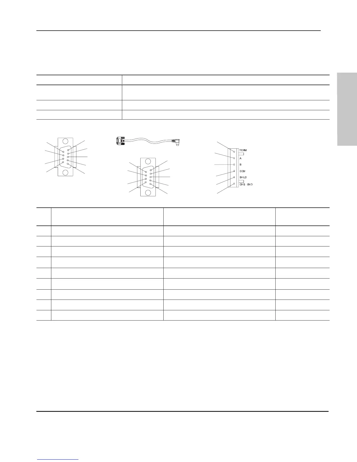
see table below for port information if making own cables
DH-485
connector Port 3
DB-9 RS-232 Port 1
cable straight D connector
1761-CBL-AP00 or 1761-CBL-PM02
Pin
Port
1
DB-9 RS-232
Port 2
➀
(1761-CBL-PM02 cable)
Port 3
DH-485 Connector
received line signal detector (DCD) same state as port 1’
s DCD signal
chassis ground
received data (RxD) received data (RxD)
cable shield
transmitted data (TxD) transmitted data (TxD)
signal ground
DTE ready (DTR)
➁
DTE ready (DTR)
➂
DH-485 data B
signal common (GRD) signal common (GRD)
DH-485 data A
DCE ready (DSR)
➁
DCE ready (DSR)
➂
termination
request to send (R
TS)
request to send (R
TS)
not applicable
clear to send (CTS) clear to send (CTS)
not applicable
not applicable not applicable not applicable
➀
An 8-pin mini DIN connector is used for making connections to port 2. This connector is not
commercially available. If you are making a cable to connect to port 2, you must configure your
cable to connect to the Allen-Bradley cable shown above.
➁
On port 1, pin 4 is electronically jumpered to pin 6. Whenever the AIC+ is powered on, pin 4 will
match the state of pin 6.
➂
In the 1761-CBL-PM02 cable, pins 4 and 6 are jumpered together within the DB-9 connector.
efesotomasyon.com - Allen Bradley,Rockwell,plc,servo,drive

 Loading...


