Connecting the System
3–13
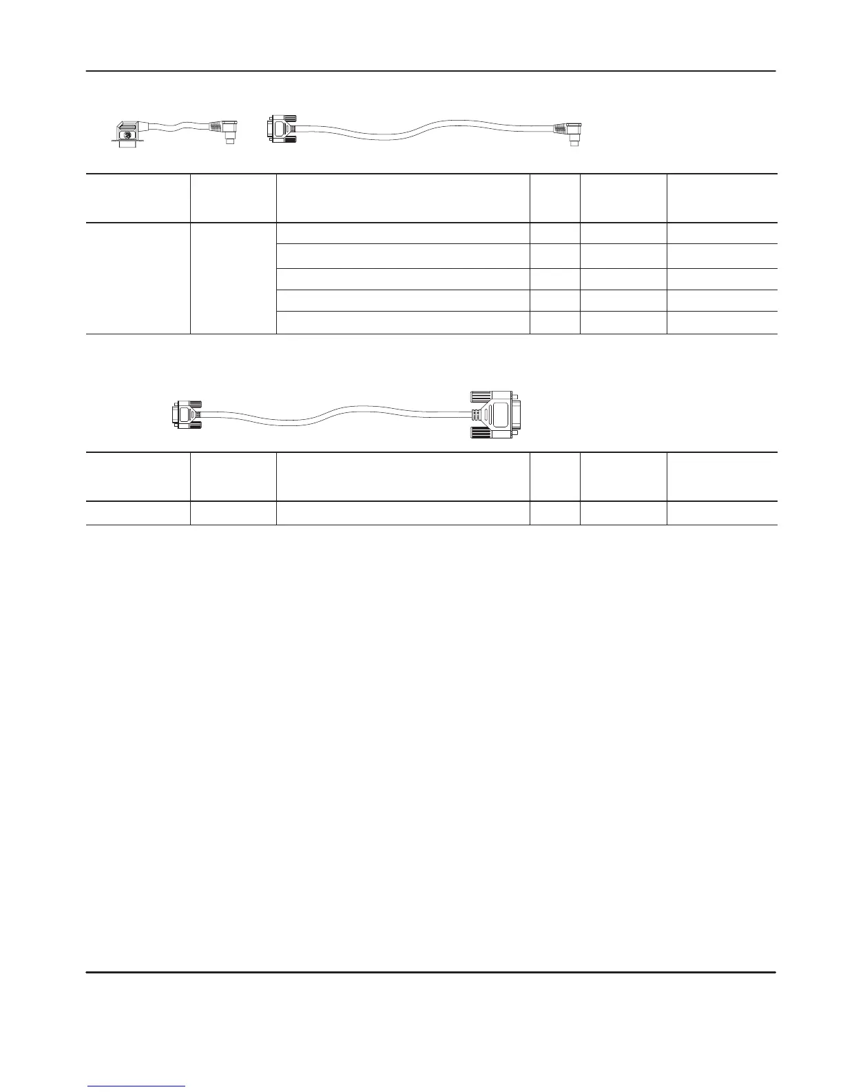
1761-CBL-PM02
➁
1761-CBL-AP00
Cable Length Connections from
to AIC+
External
Power Supply
Required
Power Selection
Switch Setting
1761-CBL-AP00
45 cm (17.7 in)
SLC 5/03 or SLC 5/04 processors, channel 0
port 2
yes external
1761-CBL-PM02
➁
2m (6.5 ft)
MicroLogix 1000
port 1
yes
➀
external
➀
PanelV
iew 550 through NULL modem adapter
port 2
yes external
DTAM Plus / DT
AM Micro
port 2
yes external
PC COM port
port 2
yes external
user
supplied cable
Cable Length Connections from
to AIC+
External
Power Supply
Required
Power Selection
Switch Setting
straight 9–25 pin
––
modem or other communication device
port 1
yes
➀
external
➀
➀
External power supply required unless the AIC+ is powered by the device connected to port 2, then
the selection switch should be set to cable.
➁
Series B or higher cables are required for hardware handshaking.
efesotomasyon.com - Allen Bradley,Rockwell,plc,servo,drive

 Loading...


