Rockwell Automation Publication 750-PM001N-EN-P - February 2017 165
Drive Port 0 Parameters Chapter 3
DIAGNOSTICS
Fault/Alarm Info
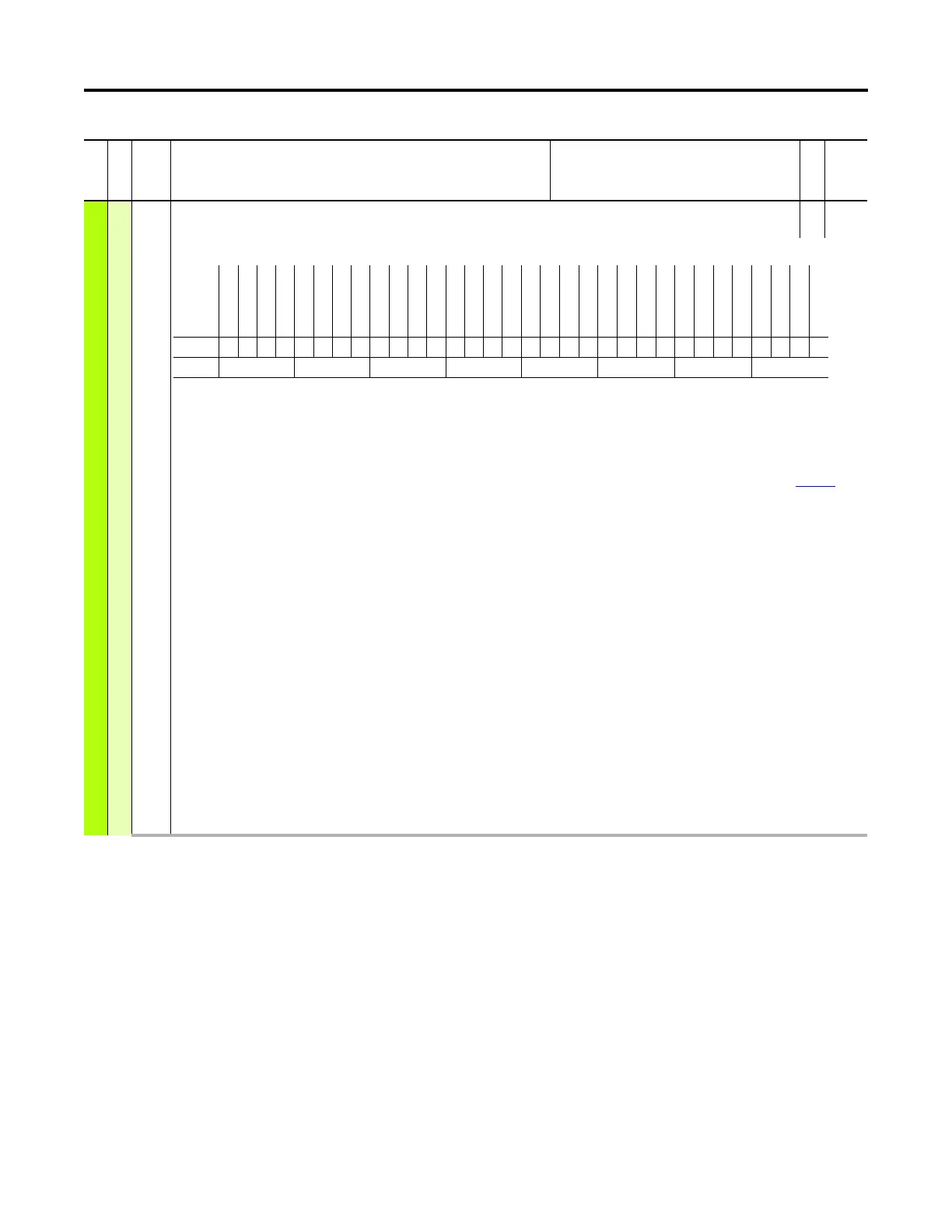
961 Type 2 Alarms
Type 2 Alarms
RO 32-bit
Integer
Indicates the occurrence of conditions that have been configured as alarms.
Bit 0 “Sleep Cfg” – The Sleep/Wake function is not configured properly. Refer to P350 [Sleep Wake Mode] for conditions required to start drive.
Bit 1 “BrakeSlipped” – The Torque Prove function encountered a Brake Slip condition.
Bit 2 “TrqProvCflct” – The Torque Prove function is not configured properly. Feedback device must be setup to fault if loss is detected and to use dual channel,
differential type encoder if encoder feedback is selected. For encoderless operation, read the Attention statement under Lifting/Torque Proving on page 356
.
Bit 3 “Frq Cflct” – Volts per Hz is not setup properly.
Bit 4 “VHzNegSlope” –
Bit 5 “VHzBoostLmt” –
Bit 6 “VHz Incmpble” –
Bit 7 “PriOpenLoop” – When set, indicates an invalid configuration has been selected and the drive will not be allowed to start. A Flux Vector control mode with
Permanent Magnet motor type has been selected, but the primary feedback selection is Open Loop. For the PF753 drive, a feedback device must be used for PM flux
vector control. For the PF755 drive, Flux Vector Open Loop control of PM motors is allowed.
Bit 8 “AltOpenLoop” – When set, indicates an invalid configuration has been selected and the drive will not be allowed to start. A Flux Vector control mode with
Permanent Magnet motor type has been selected, but the alternate feedback selection is Open Loop and the automatic tach loss switchover option is selected. For
the PF753 drive, a feedback device must be used for PM flux vector control.
Bit 9 “DigIn Cfg B” – Certain digital input functions are not allowed to be configured at the same time. For example, if you have a Run digital input configured, a
Start digital input is not allowed to be configured.
Bit 10 “DigIn Cfg C” – Multiple digital input functions configured to the same physical input is not allowed.
Bit 11 “IRVltg Range” – P73 [IR Voltage Drop] is out of range.
Bit 12 “FluxAmpsRang” – P75 [Flux Current Ref] is out of range.
Bit 13 “IXOVoltRange” – P74 [Ixo Voltage Drop] is out of range.
Bit 14 “BipolarCflct” –
Bit 15 “Prchrg Open” – Precharge relay is open.
Bit 16 “PM Off Cflct” – P80 [PM Cfg] Bit 0 “AutoOfstTest” and Bit 2 “StaticTestEn” cannot be set at the same time.
Bit 17 “DL Cflct” – There is a Datalink conflict.
Bit 18 “PM FS Cflct” – There is a permanent magnet motor, flying start conflict. A flying start sweep cannot be configured with a permanent magnet motor.
File
Group
No. Display Name
Full Name
Description
Values
Read-Write
Data Type
Options
Reserved
Reserved
Reserved
Reserved
Reserved
Reserved
Reserved
Reserved
Reserved
Reserved
Reserved
Reserved
Reserved
PM FS Cflct
DL Cflct
PM Off Cflct
Prchrg Open
BipolarCflct
(1)
(1) 753 drives only.
IXOVoltRange
FluxAmpsRang
IRVltg Range
DigIn Cfg C
DigIn Cfg B
AltOpenLoop
(1)
PriOpenLoop
(1)
VHz Incmpble
VHzBoostLmt
VHzNegSlope
Frq Cflct
TrqProvCflct
(2)
BrakeSlipped
(2)
(2) 755 drives only.
Sleep Cfg
Default00000000000000000000000000000000
Bit 313029282726252423222120191817161514131211109876543210
0 = Condition False
1 = Condition True
 Loading...


