Rockwell Automation Publication 520-UM001G-EN-E - September 2014 161
Supplemental Drive Information Appendix A
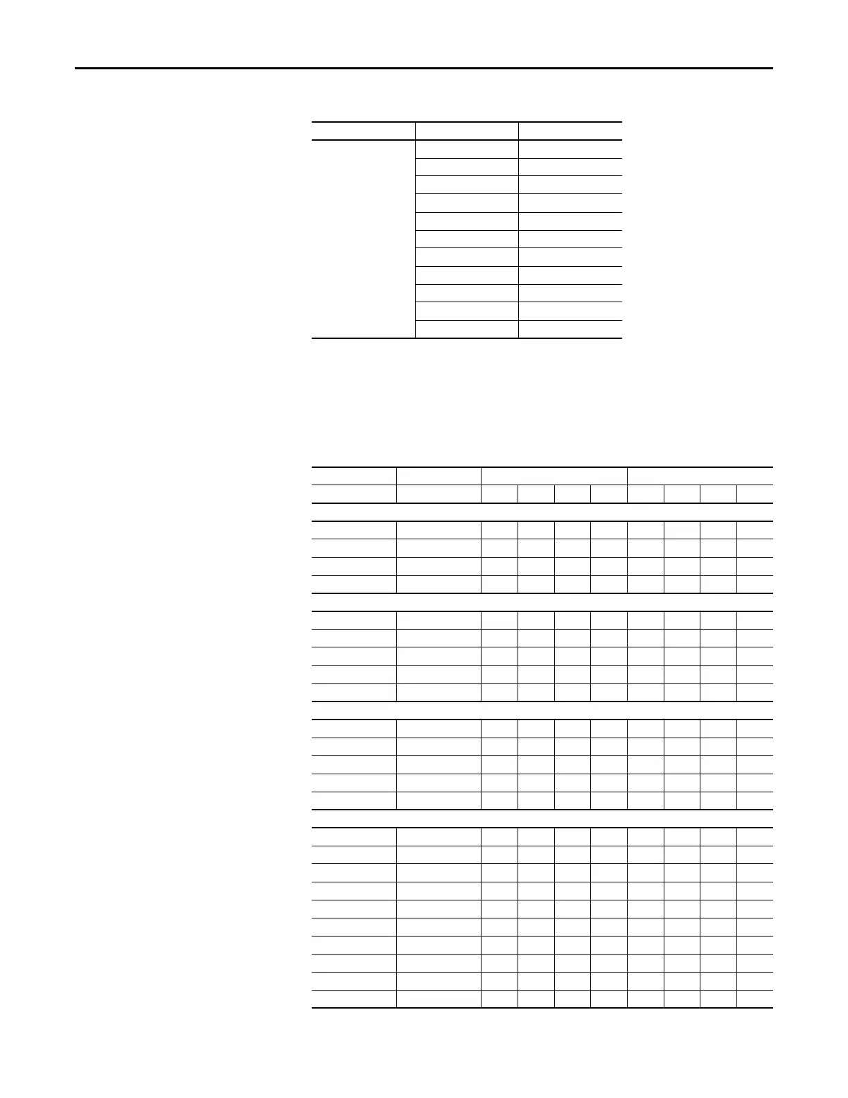
Input Current Scaling (Optional)
You can use a higher drive rating by scaling the input current based on the output
current required for your application.
525...600V,
50/60 Hz 3-Phase
0.9 22.0
1.7 32.0
3.0 50.0
4.2 65.0
6.6 95.0
9.9 138.0
12.0 164.0
19.0 290.0
22.0 336.0
27.0 466.0
32.0 562.0
PowerFlex 520-Series Input Current Scaled By Motor Current
PowerFlex 523 PowerFlex 525 Output Input
Catalog NumberCatalog Number12345678
100...120V AC (-15%, +10%) – 1-Phase Input, 0...230V 3-Phase Output
25A-V1P6N104 – 1.6 1.3 1.0 0.8 6.4 5.2 4.0 3.2
25A-V2P5N104 25B-V2P5N104 2.5 2.0 1.6 1.3 9.6 7.7 6.2 4.8
25A-V4P8N104 25B-V4P8N104 4.8 3.8 3.1 2.4 19.2 15.4 12.5 9.6
25A-V6P0N104 25B-V6P0N104 6.0 4.8 3.9 3.0 24.0 19.2 15.6 12.0
200...240V AC (-15%, +10%) – 1-Phase Input, 0...230V 3-Phase Output
25A-A1P6N104 – 1.6 1.3 1.0 0.8 5.3 4.3 3.4 2.7
25A-A2P5N104 25B-A2P5N104 2.5 2.0 1.6 1.3 6.5 5.2 4.2 3.3
25A-A4P8N104 25B-A4P8N104 4.8 3.8 3.1 2.4 10.7 8.6 7.0 5.4
25A-A8P0N104 25B-A8P0N104 8.0 6.4 5.2 4.0 18.0 14.4 11.7 9.0
25A-A011N104 25B-A011N104 11.0 8.8 7.2 5.5 22.9 18.3 14.9 11.5
200...240V AC (-15%, +10%) – 1-Phase Input with EMC Filter, 0...230V 3-Phase Output
25A-A1P6N114 – 1.6 1.3 1.0 0.8 5.3 4.3 3.4 2.7
25A-A2P5N114 25B-A2P5N114 2.5 2.0 1.6 1.3 6.5 5.2 4.2 3.3
25A-A4P8N114 25B-A4P8N114 4.8 3.8 3.1 2.4 10.7 8.6 7.0 5.4
25A-A8P0N114 25B-A8P0N114 8.0 6.4 5.2 4.0 18.0 14.4 11.7 9.0
25A-A011N114 25B-A011N114 11.0 8.8 7.2 5.5 22.9 18.3 14.9 11.5
200...240V AC (-15%, +10%) – 3-Phase Input, 0...230V 3-Phase Output
25A-B1P6N104 – 1.6 1.3 1.0 0.8 1.9 1.5 1.2 1.0
25A-B2P5N104 25B-B2P5N104 2.5 2.0 1.6 1.3 2.7 2.2 1.8 1.4
25A-B5P0N104 25B-B5P0N104 5.0 4.0 3.2 2.5 5.8 4.6 3.8 2.9
25A-B8P0N104 25B-B8P0N104 8.0 6.4 5.2 4.0 9.5 7.6 6.2 4.8
25A-B011N104 25B-B011N104 11.0 8.8 7.2 5.5 13.8 11.0 9.0 6.9
25A-B017N104 25B-B017N104 17.5 14.0 11.4 8.8 21.1 16.9 13.7 10.6
25A-B024N104 25B-B024N104 24.0 19.2 15.6 12.0 26.6 21.3 17.3 13.3
25A-B032N104 25B-B032N104 32.2 25.8 20.9 16.1 34.8 27.8 22.6 17.4
25A-B048N104 25B-B048N104 48.3 38.6 31.4 24.2 44.0 35.2 28.6 22.0
25A-B062N104 25B-B062N104 62.1 49.7 40.4 31.1 56.0 44.8 36.4 28.0
PowerFlex 520-Series Estimated Watts Loss (Rated Load, Speed & PWM)
Voltage Output Current (A) Total Watts Loss
 Loading...


