EasyManuals Logo

Allen-Bradley PowerFlex 525 User Manual

Allen-Bradley PowerFlex 525
244 pages
To Next Page IconTo Next Page
To Previous Page IconTo Previous Page
Page #186 background imageLoading...
Page #186 background image
186 Rockwell Automation Publication 520-UM001G-EN-E - September 2014
Appendix B Accessories and Dimensions
Optional Accessories and Kits
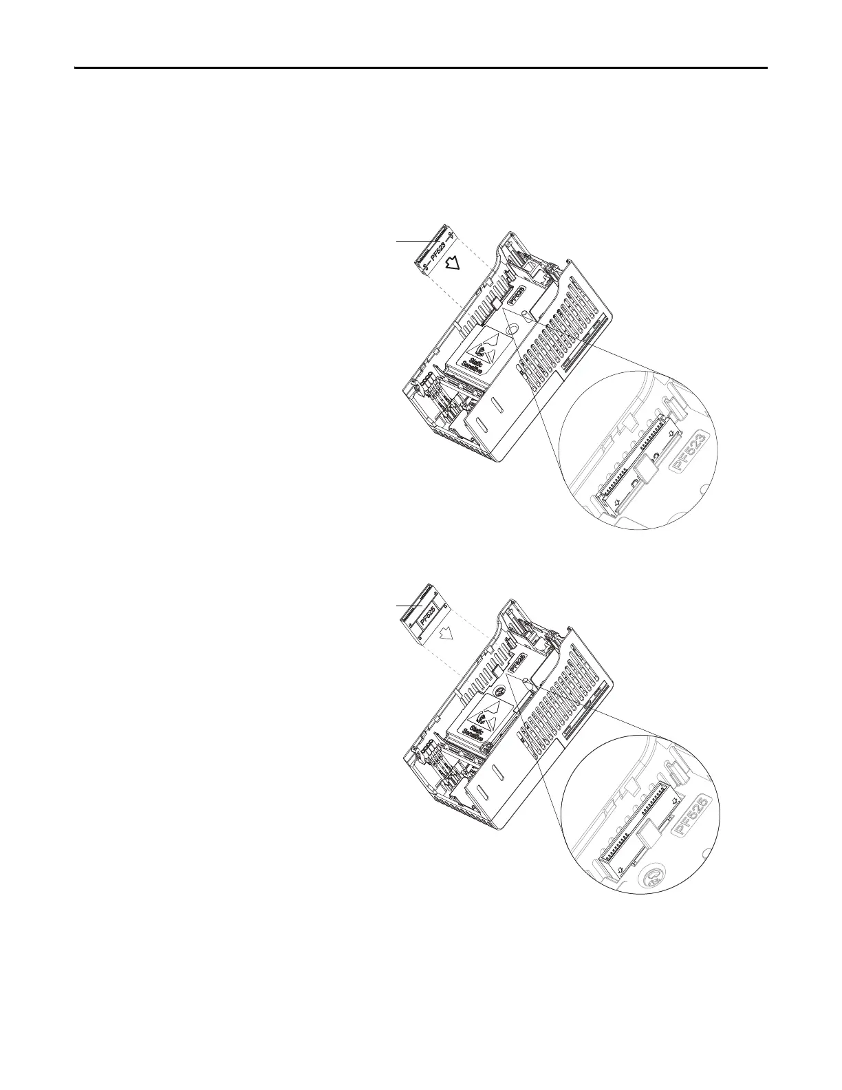
Installing a Communication Adapter
1. Insert the communication adapter interface connector into the Control
Module. Make sure the indicator line on the connector is aligned with the
surface of the Control Module.
2. Align the connectors on the communication adapter to the
communication adapter interface connector, then push the back cover
down.
Communication
adapter interface
connector
For PowerFlex 523
For PowerFlex 525
Communication
adapter interface
connector

Table of Contents

Other manuals for Allen-Bradley PowerFlex 525

Questions and Answers:

Question and Answer IconNeed help?

Do you have a question about the Allen-Bradley PowerFlex 525 and is the answer not in the manual?

Allen-Bradley PowerFlex 525 Specifications

General IconGeneral
Horsepower0.5-30 HP
kW0.4-22 kW
Input Voltage200-240V AC, 380-480V AC
EnclosureIP20, NEMA/UL Type 1
CommunicationsEtherNet/IP
Control MethodsV/Hz, Sensorless Vector
STOSafe Torque Off (STO)
Output Voltage0-Input Voltage
Operating Temperature-20°C to 50°C (-4°F to 122°F)
Storage Temperature-40°C to 85°C (-40°F to 185°F)
Relative Humidity5-95% non-condensing
DimensionsVaries by model
WeightVaries by model

Related product manuals