Rockwell Automation Publication 520-UM001G-EN-E - September 2014 229
Safe-Torque-Off Function Appendix G
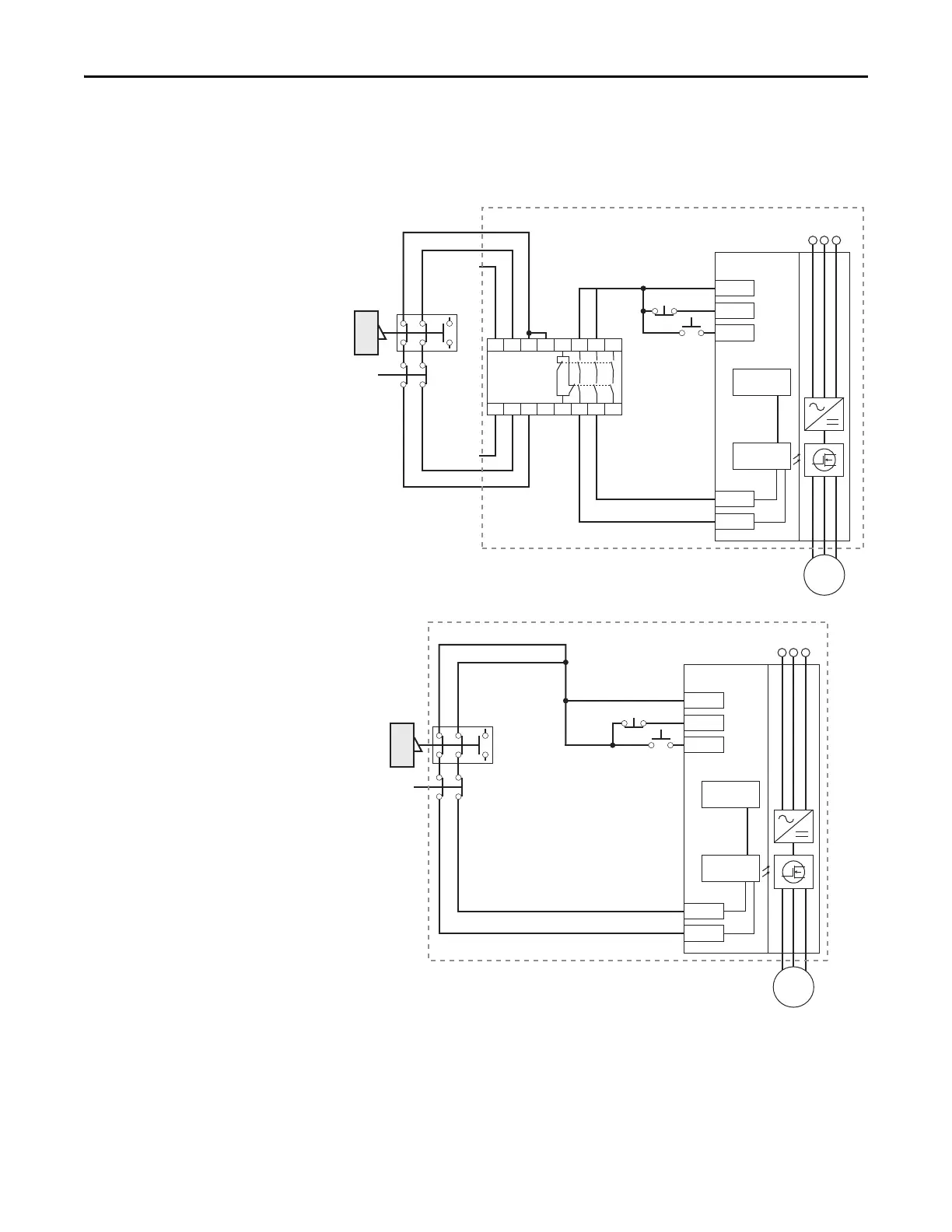
Connection Examples
Example 1 – Safe-Torque-Off Connection with Coast-to-Stop Action,
SIL 2/PL d
Stop Category 0 – Coast
(1) Enclosure Recommended. Note: External wiring failure modes must be considered as described in EN ISO 13849-2. Enclosure or
other measure to exclude these failure modes should be used.
(2) In some situations, a safety relay is not required if both the switch and PowerFlex 525 are installed in the same enclosure.
Stop
Start
A1
S21 S11 S52 41 13 23 33
A2
24V DC
common
+24V DC
S22 S14 S34 42 14 24 34
MSR
GuardMaster
Trojan
Gate
E-Stop
latching
button
+24V DC
PF 525
Stop
Start
Gate control
power supply
Gate control
circuit
AC line
input power
S1
S2
M
(1)
Stop
Start
GuardMaster
Trojan
Gate
E-Stop
latching
button
+24V DC
PF 525
Stop
Start
Gate control
power supply
Gate control
circuit
AC line
input power
S1
S2
M
(2)

 Loading...


