230 Rockwell Automation Publication 520-UM001G-EN-E - September 2014
Appendix G Safe-Torque-Off Function
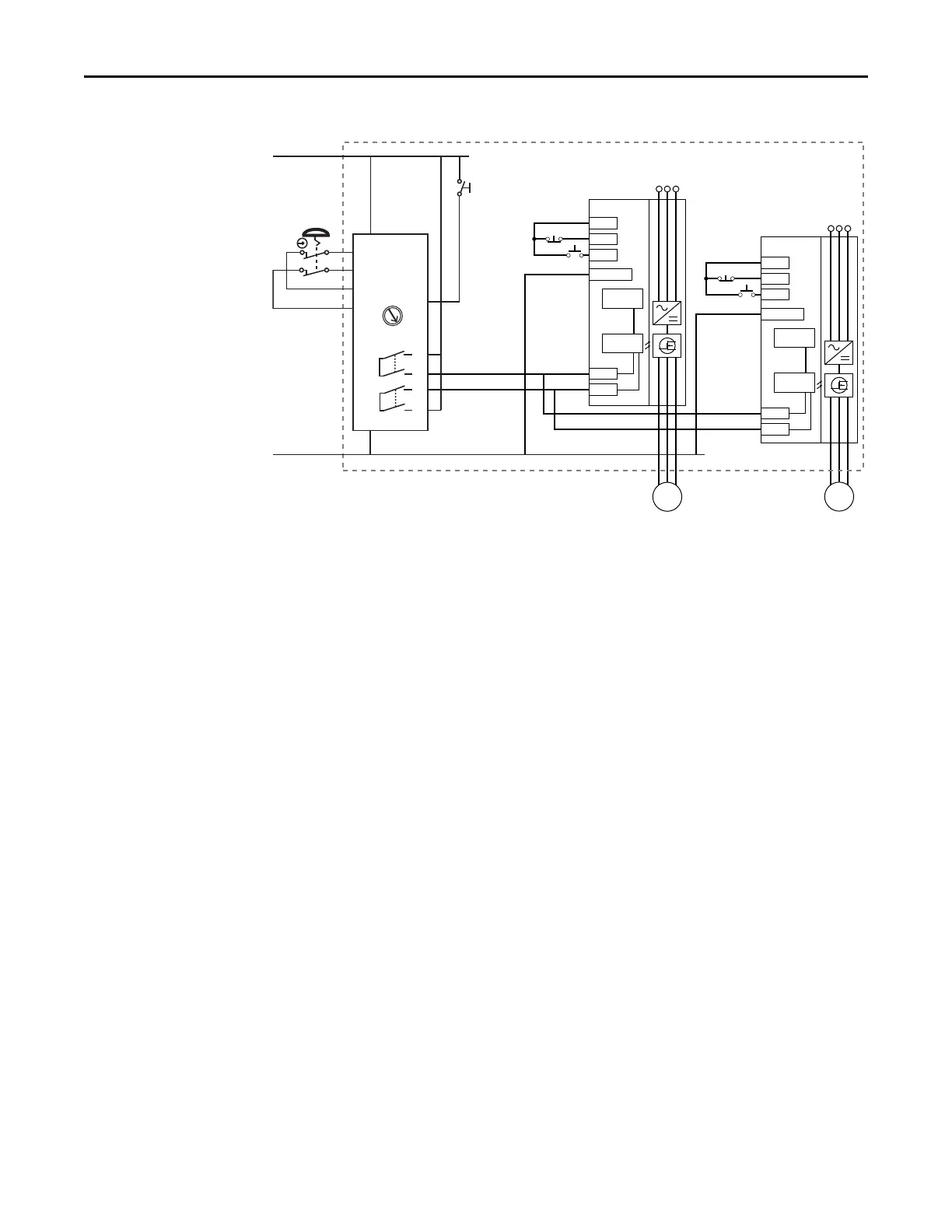
Stop Category 0 – Coast with Two PowerFlex 525 Drives
(1) Enclosure Recommended. Note: External wiring failure modes must be considered as described in EN ISO 13849-2. Enclosure or
other measure to exclude these failure modes should be used.
(2) Each safety input draws 6 mA from the supply.
Circuit Status
Circuit shown with guard door closed and system ready for normal drive
operation.
Operating Principle
This is a dual channel system with monitoring of the Safe-Torque-Off circuit and
drive. Opening the guard door will switch the input circuits (S13-S14 & S21-
S22) to the Minotaur monitoring safety relay unit. The output circuits (13-14 &
23-24) will cause the Safe-Torque-Off Enable circuit to trip and the motor will
coast to stop. To restart the drive, the Minotaur safety relay must first be reset
followed by a valid start command to the drive.
Fault Detection
A single fault detected on the Minotaur safety input circuits will result in the
lock-out of the system at the next operation and will not cause loss of the safety
function.
A single fault detected on the PowerFlex 525 safety enable redundant inputs will
result in the lock-out of the drive and will not cause loss of the safety function.
Stop
Start
+24V DC
PF 525
Stop
Start
Dig. comm
Gate control
power supply
Gate control
circuit
AC line
input power
S1
S2
M
Stop
Start
+24V DC
PF 525
Stop
Start
Dig. comm
Gate control
power supply
Gate control
circuit
AC line
input power
S1
S2
M
(1)
(2)
(2)
S11
S21
S12
S22
13
14
23
24
L11
A1
S34
L12
A2
SI
24V DC Supply
24V DC COM
E-Stop
Y32
0
AM
MM
Reset
Reset

 Loading...


