Publication 20A-IN009C-EN-P
PowerFlex® 70 Adjustable Frequency AC Drive Installation Instructions 23
In some cases a protective cover may be present over the jumper pins
that extend from the board. If present, simply remove the protective
cover, install (or remove) jumper and replace cover.
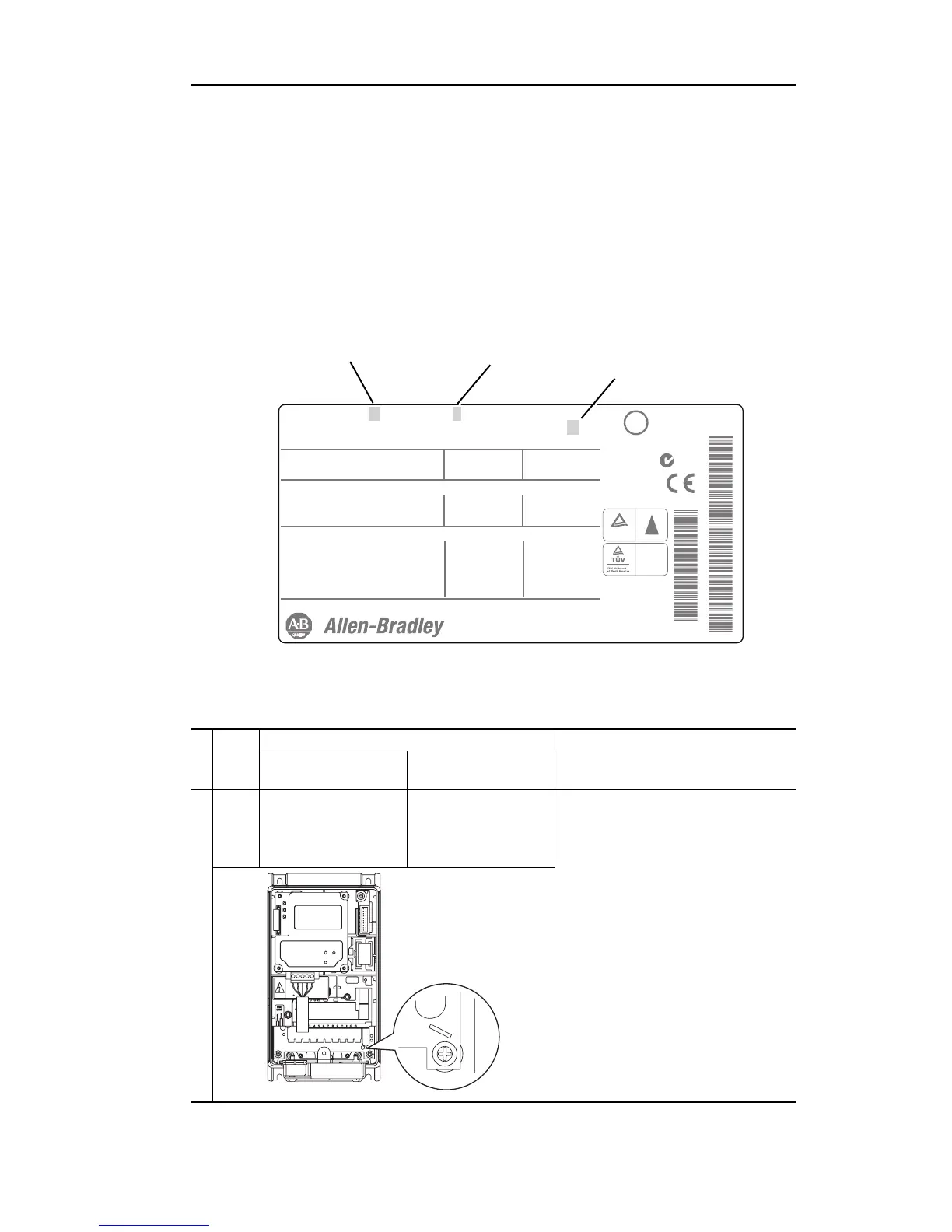
Drive Identification
Refer to the drive nameplate and locate the “Voltage Code,” “Frame” and
“Internal EMC Option” (Frame B drives). Use this information to locate
the proper procedure in the following tables.
Jumper Settings and Locations
Cat No. 20A D xxx x x xxxxxxx
Mfg. in U.S.A. (FAC1J)
UL TYPE 1/IP20 and 50C (122F) Ambient Limit
Mfd. in 2008 on Jan 19
Serial No. xxxxxxx
Series: A
Frame: A
Original Firmware No. x.xxx
LISTED INDUCTRIAL
CONTROL EQUIPMRNT
966X
U
c
US
L
?
Normal Duty Power
Heavy Duty Power
AC Voltage Range
Amps
Input: 3 Phase, 47-63Hz
Output: 3 Phase, 0-400 Hz
AC Voltage Range
Base Frequency (default)
Continuous Amps
3 Sec / 60 Sec Ovld Amps
xxx kW
xxx kW
342-440
xxx
0-400
50 Hz
xxx
xxx
xxx HP
xxx HP
432-528
xxx
400V Class
See Manual for additional ratings
480V Class
0-460
60 Hz
x
xxx / xx
N223
Serial Number
catalog number/series
TUV
Rheinland
Product Safety
..
Production inspected
W
E
C
EN 50178
Voltage Code
Internal EMC Option
Frame
Frame
Voltage
Code
Factory Default Jumper Settings
Power Source TypeMOV/Input Filter Caps
DC Bus Common
Mode Caps
A B
C
D
E
JP2/JP3
Installed
Not Applicable Solid Ground
Insert jumper at the “JP2/JP3” location.
Non-Solid Ground
Remove the jumper at “JP2/JP3.”
JP3
JP2
MOV

 Loading...


