2-80 Digital Outputs
2. The relay changes state because a particular value in the drive has
exceeded a preset limit.
The following drive values can be selected to cause the relay activation:
The balance of these functions require that the user set a limit for the
specified value. The limit is set into one of two parameters: [Dig Out1
Level] and [Dig Out2 Level] depending on the output being used. If the
value for the specified function (frequency, current, etc.) exceeds the user
programmed limit, the relay will activate. If the value falls back below
the limit, the relay will deactivate.
Notice that the [Dig Outx Level] parameters do not have units. The drive
assumes the units from the selection for the annunciated value. For
example, if the chosen “driver” is current, the drive assumes that the
entered value for the limit [Dig Outx Level] is% rated Amps. If the
chosen “driver” is Temperature, the drive assumes that the entered value
for the limit [Dig Outx Level] is degrees C. No units will be reported to
LCD HIM users, offline tools, devices communicating over a network,
PLC’s, etc.
The online and offline limits for the digital output threshold parameters
will be the minimum and maximum threshold value required for any
output condition.
If the user changes the currently selected output condition for a digital
output, then the implied units of the corresponding threshold parameter
will change with it, although the value of the parameter itself will not.
For example, if the output is set for “At Current” and the threshold for
100, drive current over 100% will activate the relay. If the user changes
the output to “At Temp”, the relay will deactivate (even if current >
100%) because the drive is cooler than 100 degrees C.
The following values can be annunciated
3. The relay changes state because a Digital Input link has been established
and the Input is closed.
Condition Description
At Speed The drive Output Frequency has equalled the commanded frequency
381
385
389
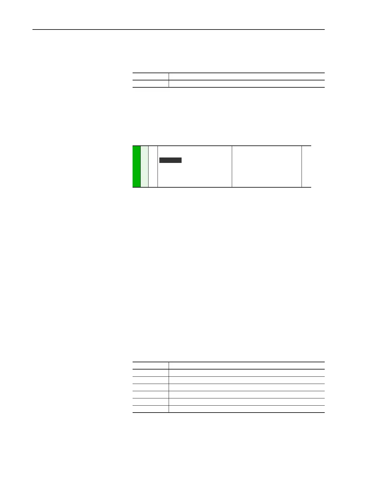
[Dig Out1 Level]
[Dig Out2 Level]
[Dig Out3 Level]
Sets the relay activation level for options
10 – 15 in [Digital Outx Sel]. Units are
assumed to match the above selection
(i.e. “At Freq” = Hz, “At Torque” = Amps).
Default:
Min/Max:
Units:
0.0
0.0
0.0/819.2
0.1
380
384
388
Value Description
At Freq The drive output frequency equals or exceeds the programmed Limit
At Current The drive total output current exceeds the programmed Limit
At Torque The drive output torque current component exceeds the programmed Limit
At Temp The drive operating temperature exceeds the programmed Limit
At Bus Volts The drive bus voltage exceeds the programmed Limit
At PI Error The drive Process PI Loop error exceeds the programmed Limit
Vector
 Loading...


