2-122 Mounting
Mounting Refer to the Chapter 1 of the correct drive User Manual for mounting
instructions and limitations. As a general rule, drives should be mounted on
a metallic flat surface in the vertical orientation. If other orientations are
being considered, contact the factory for additional data.
Notch Filter The 700 Vector has a notch filter in the torque reference loop
used to eliminate mechanical resonance created by a gear train. [Notch
Filter Freq] sets the center frequency for the 2 pole notch filter, and [Notch
Filter K] sets the gain.
Figure 2.23 Notch Filter Frequency
Due to the fact that most mechanical frequencies are described in Hertz,
[Notch Filter Freq] and [Notch Filter K] are in Hertz as well. The following
is an example of a notch filter.
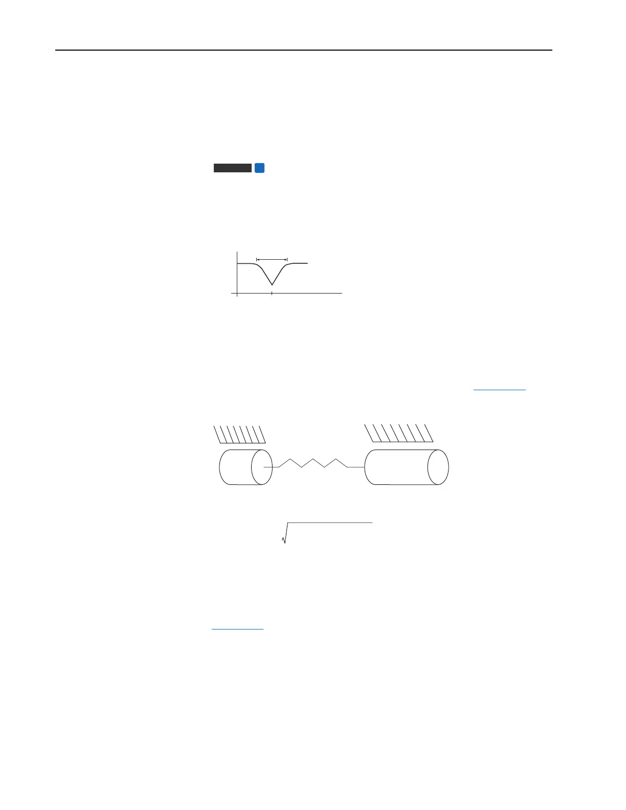
A mechanical gear train consists of two masses (the motor and the load) and
spring (mechanical coupling between the two loads). See Figure 2.24
.
Figure 2.24 Mechanical Gear Train
The resonant frequency is defined by the following equation:
Figure 2.25
shows a two mass system with a resonant frequency of 62
radians/second (9.87 Hz). One Hertz is equal to 2ðπ radians/second.
Vector
FV
Gain
0 db
Hz
Notch Filter Frequency
Notch Filter K
Kspring
BLBm
Jm Jload
Jm is the motor inertia (seconds)
Jload is the load inertia (seconds)
Kspring is the coupling spring constant (rad
2
/sec)
resonance Kspring
Jm Jload+()
Jm Jload×
---------------------------------
=

 Loading...


