Scale Blocks 2-157
Scale Blocks See also Analog Scaling on page 2-12 and page 2-22.
Scale blocks are used to scale a parameter value. [Scalex In
Value] is linked to the parameter that you wish to scale. [Scalex In Hi]
determines the high value for the input to the scale block. [Scalex Out Hi]
determines the corresponding high value for the output of the scale block.
[Scalex In Lo] determines the low value for the input to the scale block.
[Scalex Out Lo] determines the corresponding low value for the output of
the scale block. [Scalex Out Value] is the resulting output of the scale block.
There are (3) ways to use the output of the scale block:
1. A linkable destination parameter can be linked to [Scalex Out Value].
See Example Configuration #1
.
2. [Analog Outx Sel] can be set to:
– 20, “Scale Block1”
– 21, “Scale Block2”
– 22, “Scale Block3”
– 23, “Scale Block4”
Note that when the Analog Outputs are set to use the scale blocks, the
[Scale x Out Hi] and [Scale x Out Lo] parameters are not active. Instead,
[Analog Outx Hi] and [Analog Outx Lo] determine the scaling for the
output of the scale block. See Example Configuration #2
.
3. [PI Reference Sel] and [PI Feedback Sel] can also use the output of the
scale block by setting them to:
– 25, “Scale Block1 Out”
– 26, “Scale Block2 Out”
Note that when [PI Reference Sel] and [PI Feedback Sel] are set to use
the scale blocks, the [Scale x Out Hi] and [Scale x Out Lo] parameters
are not active. Instead, [PI Reference Hi] and [PI Reference Lo], or [PI
Feedback Hi] and [PI Feedback Lo], determine the scaling for the output
of the scale block. See Example Configuration #3
.
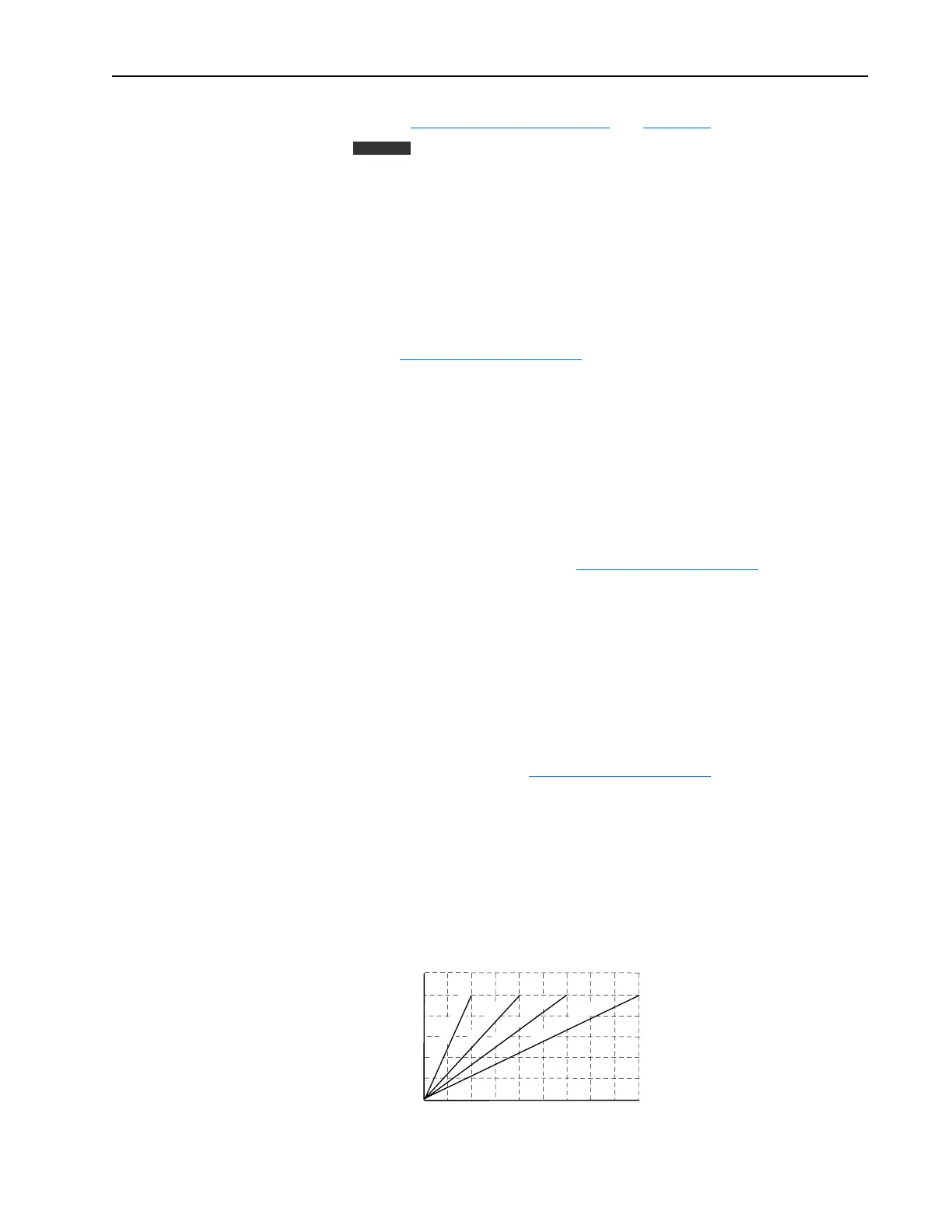
Example Configuration #1
Use the scale blocks to add a speed trim as a percentage of the speed
reference instead of as a percent of full speed. Analog In 2 will be used to
provide a 0-10V DC trim signal. For example, when the commanded speed
is 800 RPM, the maximum trim with 10V DC at Analog In 2 will be 80
RPM. If the commanded speed is 1800 RPM the maximum trim will be 180
RPM.
Vector
Cmd Spd = 400 RPM
Cmd Spd = 800 RPM
Cmd Spd = 1200 RPM
Cmd Spd = 1800 RPM
0
0
2
4
6
8
10
20 40 60 80 100 120 140 180
Preset Speed 1 (RPM)
Scale1 In Value =
Analog In2 Val (Volts)
 Loading...


