2-88 Drive Overload
Thermal Manager Protection
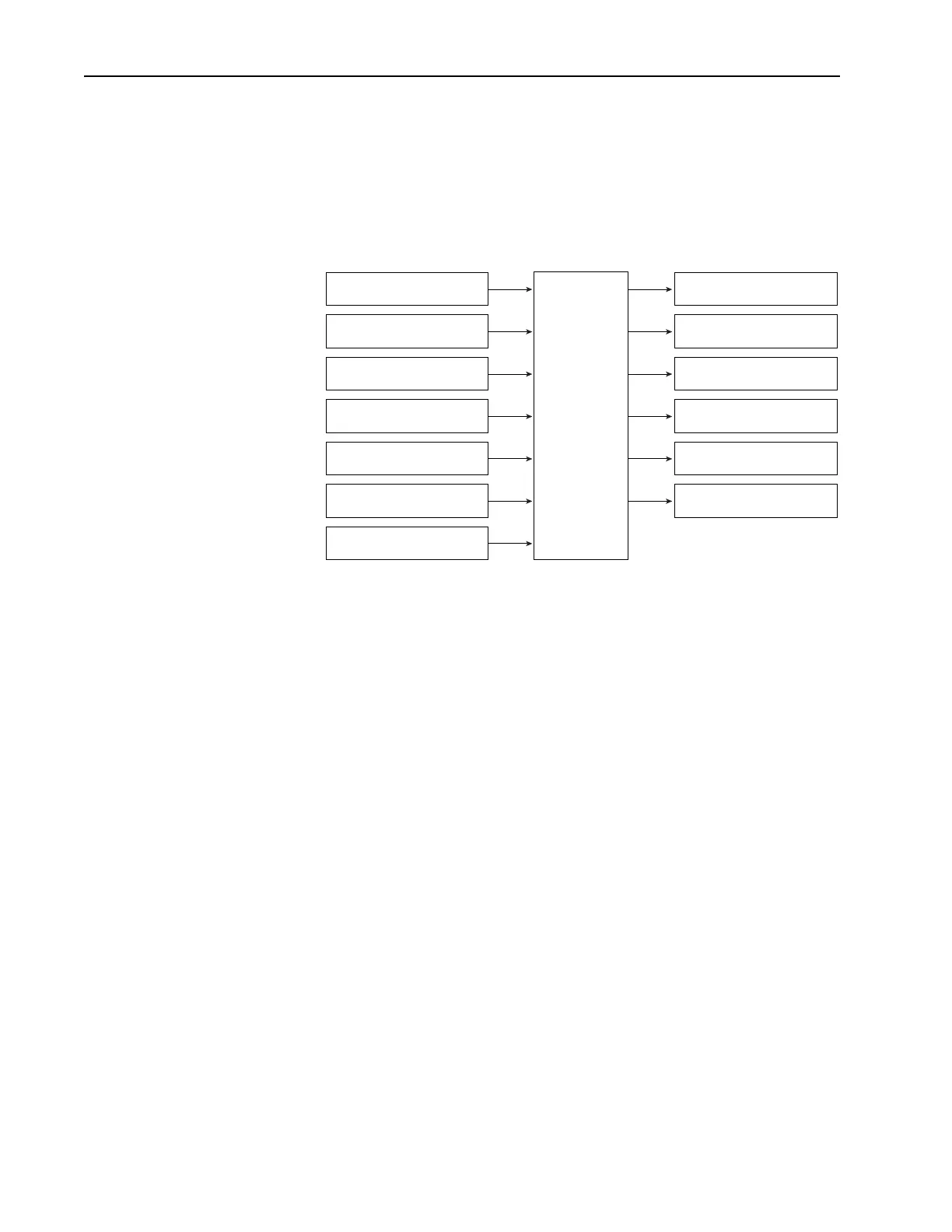
The thermal manager protection assures that the thermal ratings of the
power module are not exceeded. The operation of the thermal manager can
be thought of as a function block with the inputs and outputs as shown
below.
Figure 2.20 Thermal Manager Inputs/Outputs
The following is a generalization of the calculations done by the thermal
manager. The IGBT junction temperature T
J
is calculated based on the
measured drive temperature T
Drive
, and a temperature rise that is a function
of operating conditions. When the calculated junction temperature reaches a
maximum limit the drive will generate a fault. This fault can not be
disabled. This maximum junction temperature is stored in EE on the power
board along with other information to define the operation of the drive
thermal overload function. These values are not user adjustable. In addition
to the maximum junction temperature there are thresholds that select the
point at which the PWM frequency begins to fold back, and the point at
which current limit begins to fold back. As T
J
increases the thermal
manager may reduce the PWM frequency. If T
J
continues to rise current
limit may be reduced, and if T
J
continues to rise the drive generates a fault.
The calculation of the reduced PWM frequency and current limit is
implemented with an integral control.
PWM Frequency
PWM Frequency as selected by the user can be reduced by the thermal
manager. The resulting Active PWM Frequency may be displayed in a test
point parameter.
The active PWM frequency will change in steps of 2 kHz. It will always be
less than or equal to the value selected by the user, and will not be less than
the drives minimum PWM frequency. When drive temperature reaches the
level where PWM frequency would be limited, the Drv OL Lvl 1 Alarm is
turned on. This alarm will be annunciated even if the reduced PWM
frequency is not enabled.
PWM Frequency
(2 - 12 kHz)
Output Frequency
(0-400 Hz)
Temperature Analog Input
(Volts)
DT O Select
(Off,PWM,ILmt,Both)
Current Limit
(0 - 200%)
EE Power Board Data
IGBT Temperature
(x deg C)
Drive Temperature
(x deg C)
DTO Fault
(On,Off)
Active PWM Frequency
(2 - 12 kHz)
Active Current Limit
(0 - 200%)
I_ t ot al
(Amps)
V_dc
(Volts)
ILmt Alarm
(On, Off)
KHz Alarm
(On, Off)
Drive
Thermal
Overload
 Loading...


