2-16 Analog Inputs
Configuration #6 – Torque Ref:
• [Anlg In Config], bit 0 = “0” (Voltage)
• [Torque Ref A Sel] = “Analog In 1”
• [Torque Ref A Hi] = 200%
• [Torque Ref A Lo] = 0%
• [Torque Ref A Div] = 1
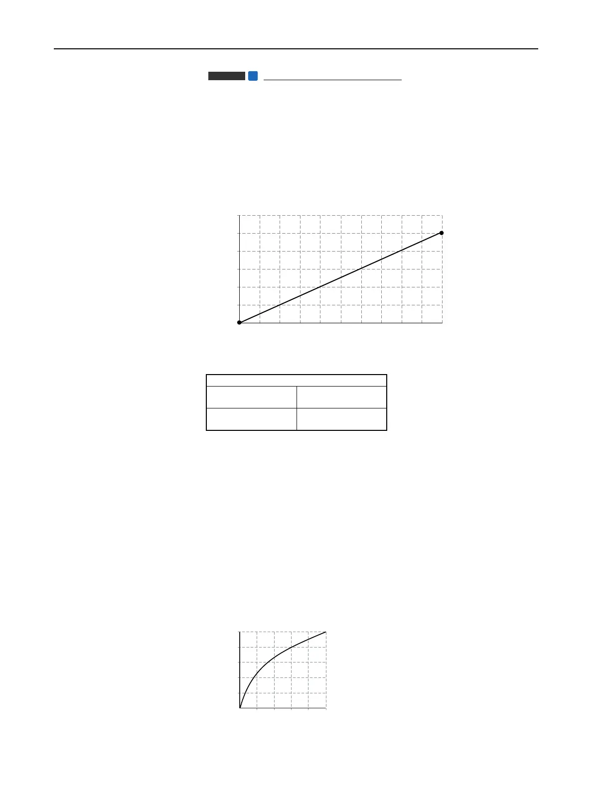
This configuration is used when the input signal is 0-10 volts. The minimum
input of 0 volts represents a torque reference of 0% and maximum input of
10 volts represents a torque reference of 200%.
Square Root
[Anlg In Sqr Root]
For both analog inputs, the user can enable a square root function for an
analog input through the use of [Analog In Sq Root]. The function should
be set to enabled if the input signal varies with the square of the quantity
(i.e. drive speed) being monitored.
If the mode of the input is bipolar voltage (–10v to 10v), then the square
root function will return 0 for all negative voltages.
The square root function is scaled such that the input range is the same as
the output range. For example, if the input is set up as a unipolar voltage
input, then the input and output ranges of the square root function will be 0
to 10 volts, as shown in figure below.
Analog Scaling
[Torque Ref A Sel] = “Analog In 1”
[Analog In 1 Hi]
10V
[Torque Ref A Hi]
200%
[Analog In 1 Lo]
0V
[Torque Ref A Lo]
0%
Vector
FV
2
4
6
8
10
12
2004060
Torque Ref %
Input Volts
80 100 120 140 160 180 200
2
4
6
8
10
2046
Input (Volts)
Output (Volts)
810

 Loading...


