Analog Inputs 2-19
How [Analog Inx Hi/Lo] & [Speed Ref A Hi/Lo] Scales the Frequency
Command Slope with [Minimum/Maximum Speed]
Example 1:
Consider the following setup:
• [Anlg In Config], bit 0 = “0” (voltage)
• [Speed Ref A Sel] = “Analog In 1”
• [Analog In1 Hi] = 10V
• [Analog In1 Lo] = 0V
• [Speed Ref A Hi] = 60 Hz
• [Speed Ref A Lo] = 0 Hz
• [Maximum Speed] = 45 Hz
• [Minimum Speed] = 15 Hz
This operation is similar to the 0-10 volts creating a 0-60 Hz signal until the
minimum and maximum speeds are added. [Minimum Speed] and
[Maximum Speed] limits will create a command frequency deadband.
This deadband, as it relates to the analog input, can be calculated as follows:
1. The ratio of analog input volts to frequency (Volts/Hz) needs to be
calculated. The voltage span on the analog input is 10 volts. The
frequency span is 60 Hz.
2. Determine the frequency span between the Minimum and Maximum
Speed limits and Speed Ref A Hi and Lo.
3. Multiply by the Volts/Hertz ratio
Therefore the command frequency from 0 to 2.5 volts on the analog input
will be 15 Hz. After 2.5 volts, the frequency will increase at a rate of
0.16667 volts per hertz to 7.5 volts. After 7.5 volts on the analog input the
frequency command will remain at 45 Hertz.
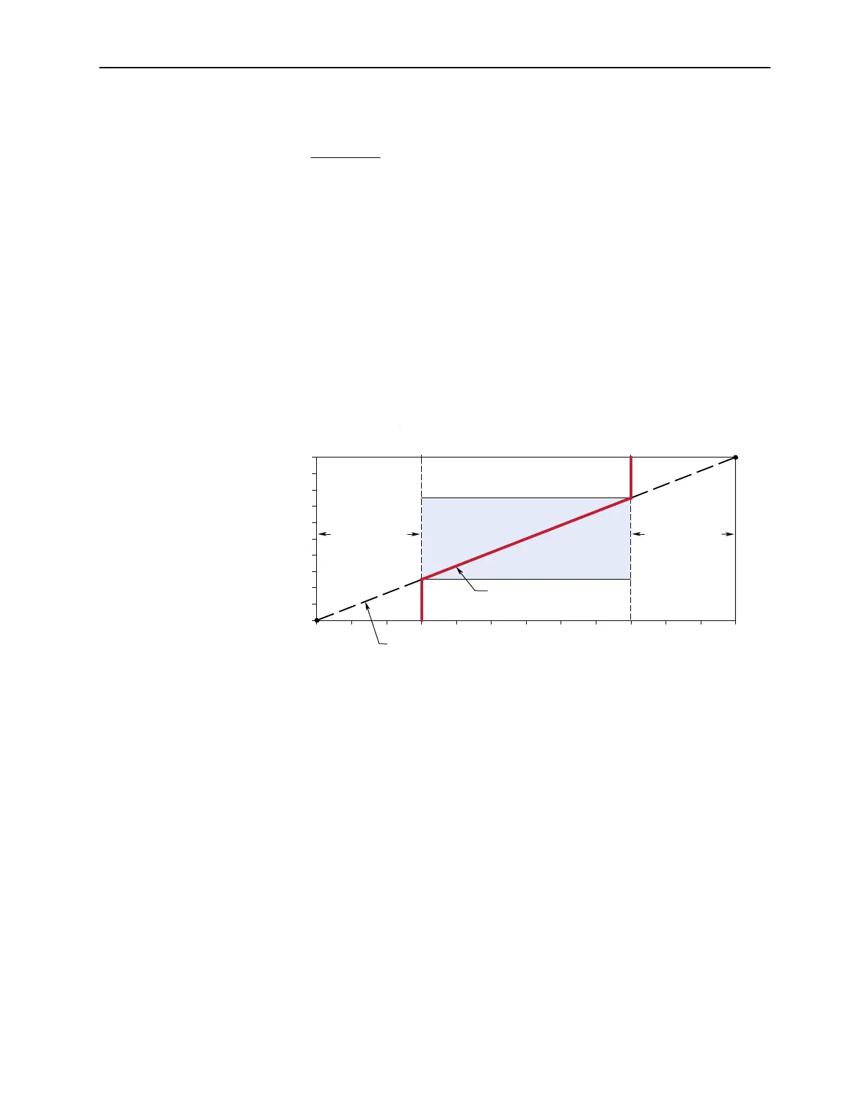
Motor Operating Range
Command Frequency
15 Hz 45 Hz 60 Hz0 Hz
Frequency Deadband
Slope defined by (Analog Volts)/(Command Frequency)
Frequency Deadband
7.5-10 Volts0-2.5 Volts
[Speed Ref A Lo] [Speed Ref A Hi]
10V
0V
[Analog In1 Hi]
[Analog In1 Lo]
[Maximum Speed][Minimum Speed]
10 Volts/60 Hz = 0.16667 Volts/Hz
[Speed Ref A Hi] – [Maximum Speed] = 60 – 45 = 15 Hz and . . .
[Minimum Speed] – [Speed Ref A Lo] = 15 – 0 = 15 Hz.
15 Hz x 0.16667 Volts/Hz = 2.5 Volts

 Loading...


