Summary of Changes
The information below summarizes the changes to the PowerFlex 70/700
Reference Manual, publication PFLEX-RM001 since the last release.
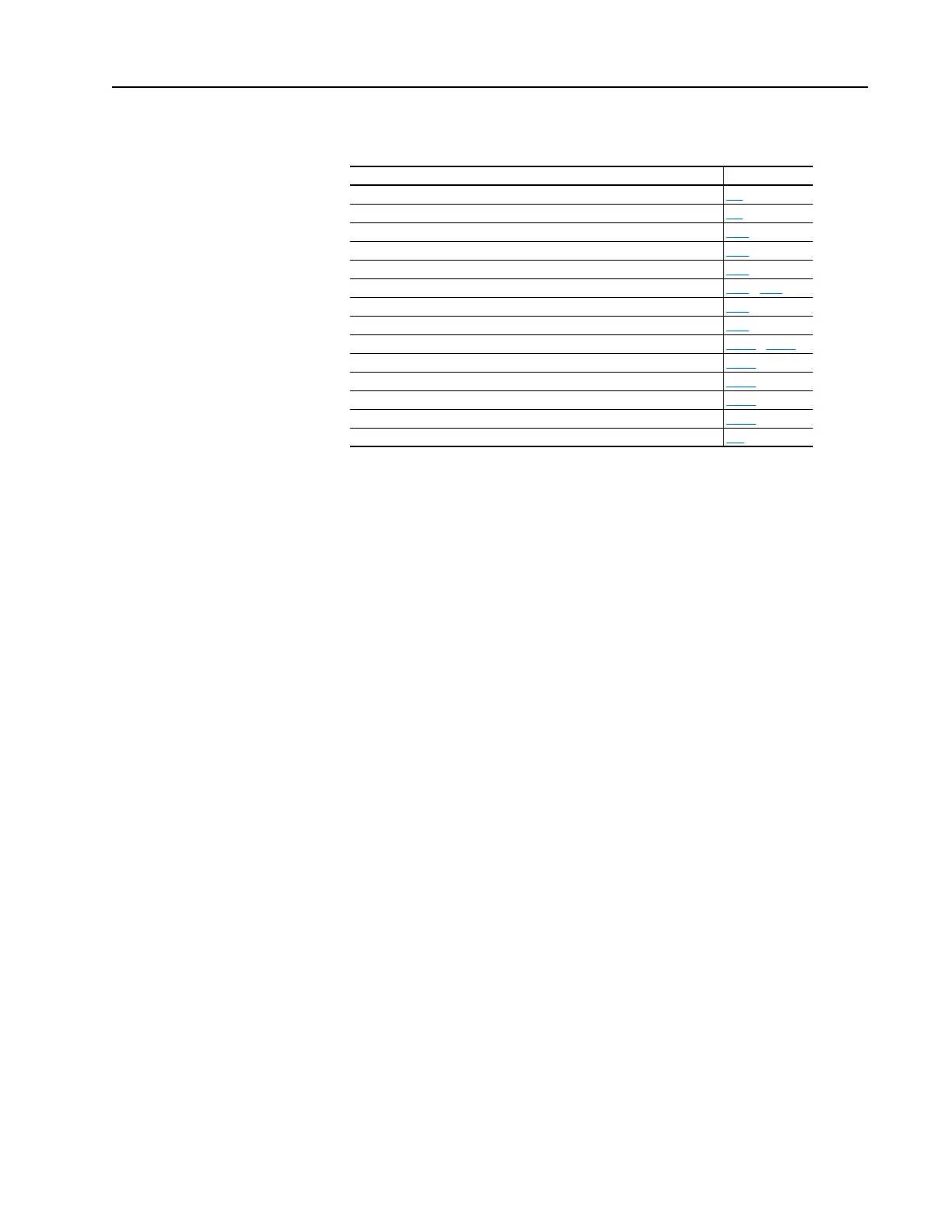
Change Page
PowerFlex 700 60 HP, 600V Derate added 1-6
PowerFlex 70 dimensions updated 1-7
PowerFlex 700 Frame 4 dimensions updated 1-14
Analog Input Cable Selection updated 2-18
PowerFlex 700 Analog Output info added for firmware 3.001 & later 2-24
“Bus Regulation” section updated 2-49 - 2-51
Digital Input Cable Selection updated 2-61
PowerFlex 700 Digital Output info added for firmware 3.001 & later 2-82
Fuse & Circuit Breaker tables updated 2-101 - 2-106
Bypass Contactor Attention statement added 2-121
PowerFlex 700 Process PI info added for firmware 3.001 & later 2-150
Scale Blocks sections added 2-157
PowerFlex 700 Torque Reference info added for firmware 3.001 & later 2-209
Dynamic Brake Selection Guide updated A-1

 Loading...


