PowerFlex 700 Technical Data
20B-TD001F-EN-P 25
Fan Transformer Specifications/Fusing
Three-Phase Blower Fusing
Additional Frame 10 Wiring Requirement for IP00 AC Input Drives
The Inverter and Converter sections of Frame 10 AC Input IP00, NEMA/UL Type Open drives are shipped separately.
Once installed, the following connections will be required.
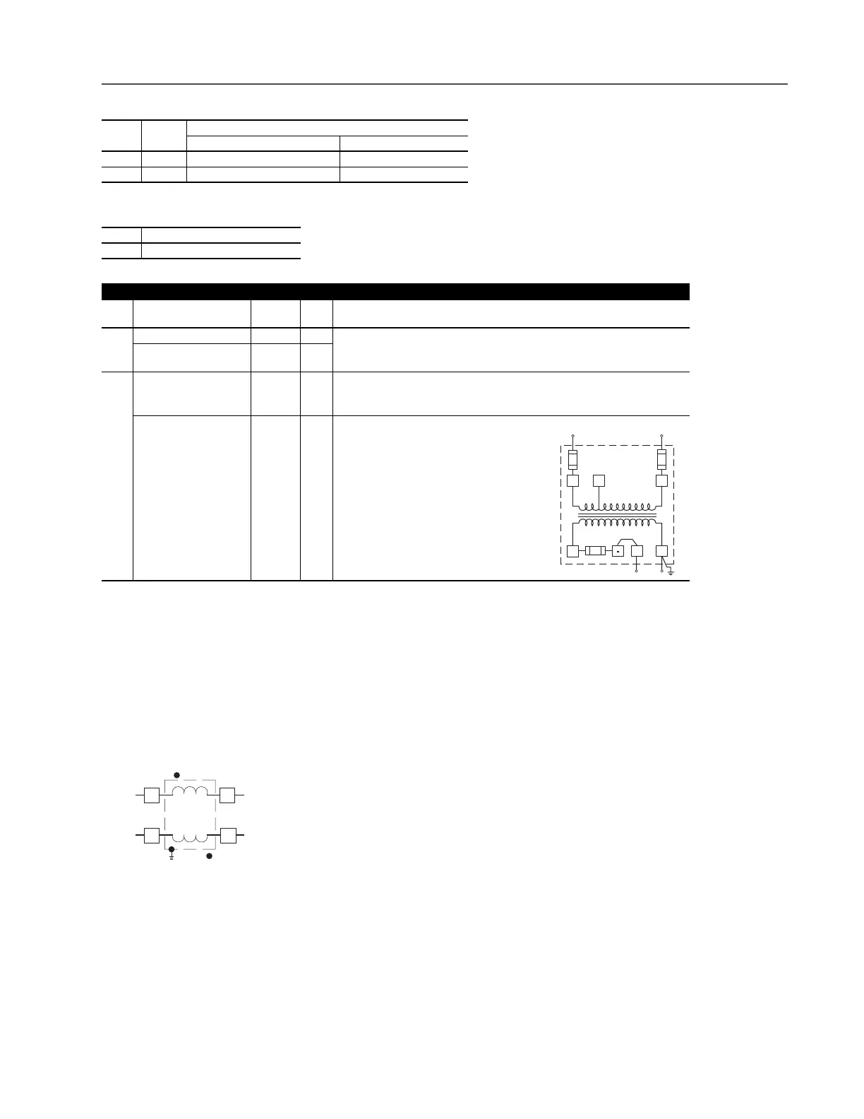
1. DC Link Choke Wiring
DC link chokes are supplied loose for customer mounting and wiring in IP00 drives. Refer to the figure below for
connection information and page 32 for drive ratings.
DC Link Choke Wiring
2. Thermistor Wiring
Thermistor wiring will be coiled loose in the Converter section for shipping. Locate the wire (labeled “To INV”) and
route through the enclosure wall. Connect it to the mating connector located above the HIM cradle.
3. Ground the drive chassis
Frame Rating
Recommended Fuses
Primary (Quantity 2) Secondary (Quantity 1)
8 & 9 500 VA 2.8A, 600V AC, KLDR/ATQR Type 6.25A, 250V AC, Time Delay
10 1000 VA 6A, 600V AC, KLDR/ATQR Type 9A, 250V AC, Time Delay
Frame Recommended Fuses (Quantity 3)
9 5A, 600V AC, Time Delay
Frame 10 Fan Connections
Drive
Type Enclosure
Rating
(120VAC)
No. of
Fans Connect at …
DC
Input
IP00, NEMA/UL Type Open 1000 VA 2 TB9 & 10
Requires user supplied 120V AC. See page 21 for TB locations and page 24 for
terminal designations.
IP20, NEMA/UL Type 1 1000 VA 2
AC
Input
IP00, NEMA/UL Type Open 1000 VA 3 TB9, 10 & 12
Requires user supplied 120V AC. See page 21 for TB locations and page 24 for
terminal designations.
IP20, NEMA/UL Type 1 1000 VA 3 TB9, 10 & 12
A transformer matches the input line voltage to the
internal fan voltage. If line voltage is different than
the voltage class specified on the drive nameplate,
it may be necessary to change transformer taps.
Input Line Voltage
480/400V AC, 50/60 Hz
F2
H3
480 400
F3
to TB9
JMP
0
115 0
F1
H2H1
X1 XF X2
Output to Inverter
Capacitor Bank
Input from
Converter
CNV+
CNV–
INV+
(1) (2)
(4) (3)
INV–
DC–
DC+
to Mounting Foot

 Loading...


