EasyManuals Logo

Allen-Bradley powerflex 700 Technical Data

Allen-Bradley powerflex 700
82 pages
To Next Page IconTo Next Page
To Previous Page IconTo Previous Page
Page #55 background imageLoading...
Page #55 background image
PowerFlex 700 Technical Data
20B-TD001F-EN-P 55
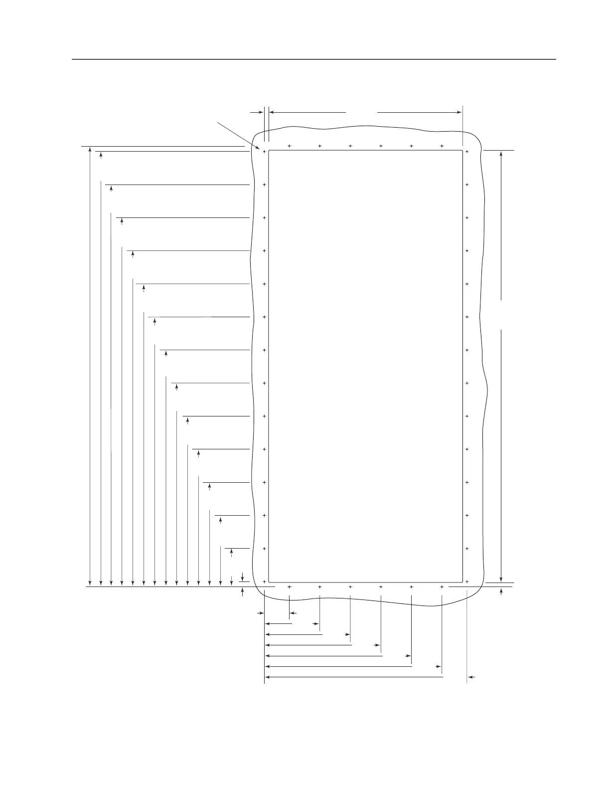
Frame 5 Flange Mount Cutout
Dimensions are in millimeters and (inches)
10.0
(0.39)
458.0
(18.03)
4.00 (0.157) Dia. Holes (40 Places)
in Minimum 14 GA. (1.9) Steel
Mounting Surface. Deburr Pilot Holes
and Drive Cutout.
1019.0
(40.12)
Cutout
1039.0
(40.91)
1026.5
(40.41)
948.5
(37.34)
870.5
(34.27)
792.5
(31.20)
714.5
(28.13)
636.5
(25.06)
558.5
(21.99)
480.5
(18.92)
402.5
(15.85)
324.5
(12.78)
246.5
(9.71)
168.5
(6.63)
90.5
(3.56)
12.5
(0.49)
59.0
(2.32)
131.0
(5.16)
203.0
(7.99)
275.0
(10.83)
347.0
(13.66)
419.0
(16.50)
478.0
(18.82)
10.0
(0.39)

Other manuals for Allen-Bradley powerflex 700

Questions and Answers:

Question and Answer IconNeed help?

Do you have a question about the Allen-Bradley powerflex 700 and is the answer not in the manual?

Allen-Bradley powerflex 700 Specifications

General IconGeneral
SeriesPowerFlex 700
CategoryAC Drive
Input Voltage200-240V AC, 380-480V AC, 500-600V AC
EnclosureType 1
Control MethodSensorless Vector
CommunicationEtherNet/IP, ControlNet, DeviceNet, PROFIBUS DP, Modbus

Related product manuals