PowerFlex 700 Technical Data
56 20B-TD001F-EN-P
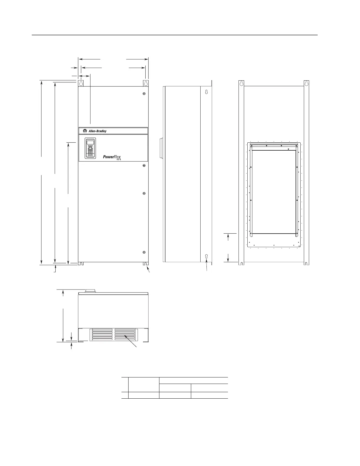
Frame 6 NEMA/UL Type 12 Stand-alone – 400…690V Only
Dimensions are in millimeters and (inches)
Frame
Description
Approx. Weight
(1)
kg (lbs.)
(1)
Weights include HIM and Standard I/O.
Drive Drive & Packaging
6 Stand-alone 176.90 (390.0) 229.07 (505.0)
663.1 (26.10)
24.1 (0.90)
123.6 (4.90)
1828.8
(72.00)
1279.5
(50.40)
16.8 (0.66)
1795.2
(70.70)
487.8
(19.20) Max.
Air Inlet
711.3 (28.00)
13.5 (0.53) Dia.
4 Places (See Note A)
12.7 (0.50) Dia.
Lifting Holes
283.3
(11.20)
8.0
(0.30)
Note A:
Mount with 0.50 Inch UNC Grade 5 or Higher Screws
or
M12 Material Class 5.6 or Higher Screws
Use Flat Washer with each Fastener

 Loading...


