PowerFlex 700 Technical Data
20B-TD001F-EN-P 57
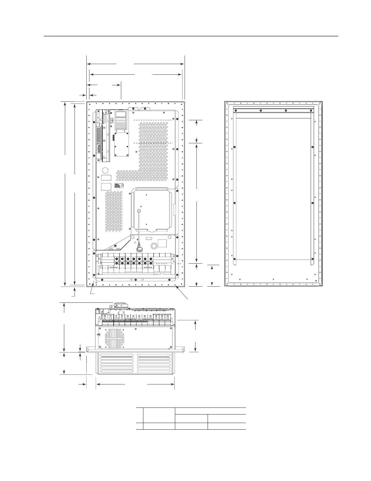
Frame 6 NEMA/UL Type 12 Flange Mount – 400…690V Only
Dimensions are in millimeters and (inches)
Frame
Description
Approx. Weight
(1)
kg (lbs.)
(1)
Weights include HIM and Standard I/O.
Drive Drive & Packaging
6 Flange Mount 99.79 (220.0) 119.75 (264.0)
U
T1
DC-DC+BR1BR2 V
T2
W
T3
R
L1
S
L2
OUTPUT
T
L3
PE PE
USE 75C COPPER WIRE ONLY, TORQUE 52 IN-LB (6 N-M)
22-12 AWG
5.3 IN-LB
(0.6 N-M)
PS+
PS-
WIRE STRIP
584.0
(23.00)
14.0
(0.60)
556.0
(21.90)
201.0
(7.90)
1100.0
(43.30)
1078.0
(42.40)
11.0
(0.43)
5.5 (0.22) Dia. Holes for
Supplied Mounting Hardware
44 Places
127.3
(5.00)
763.3
(30.0)
105.8
(4.17)
137.2
(5.40)
294.7
(11.60)
2.4 (0.10)
Compressed
Gasket
131.6
(5.20)
468.2
(18.40)
57.9
(2.30)
193.7
(7.60)
Ground
M5 PEM Stud

 Loading...


