Rockwell Automation Publication 750-RM003A-EN-P - April 2018 57
Selection Considerations Chapter 1
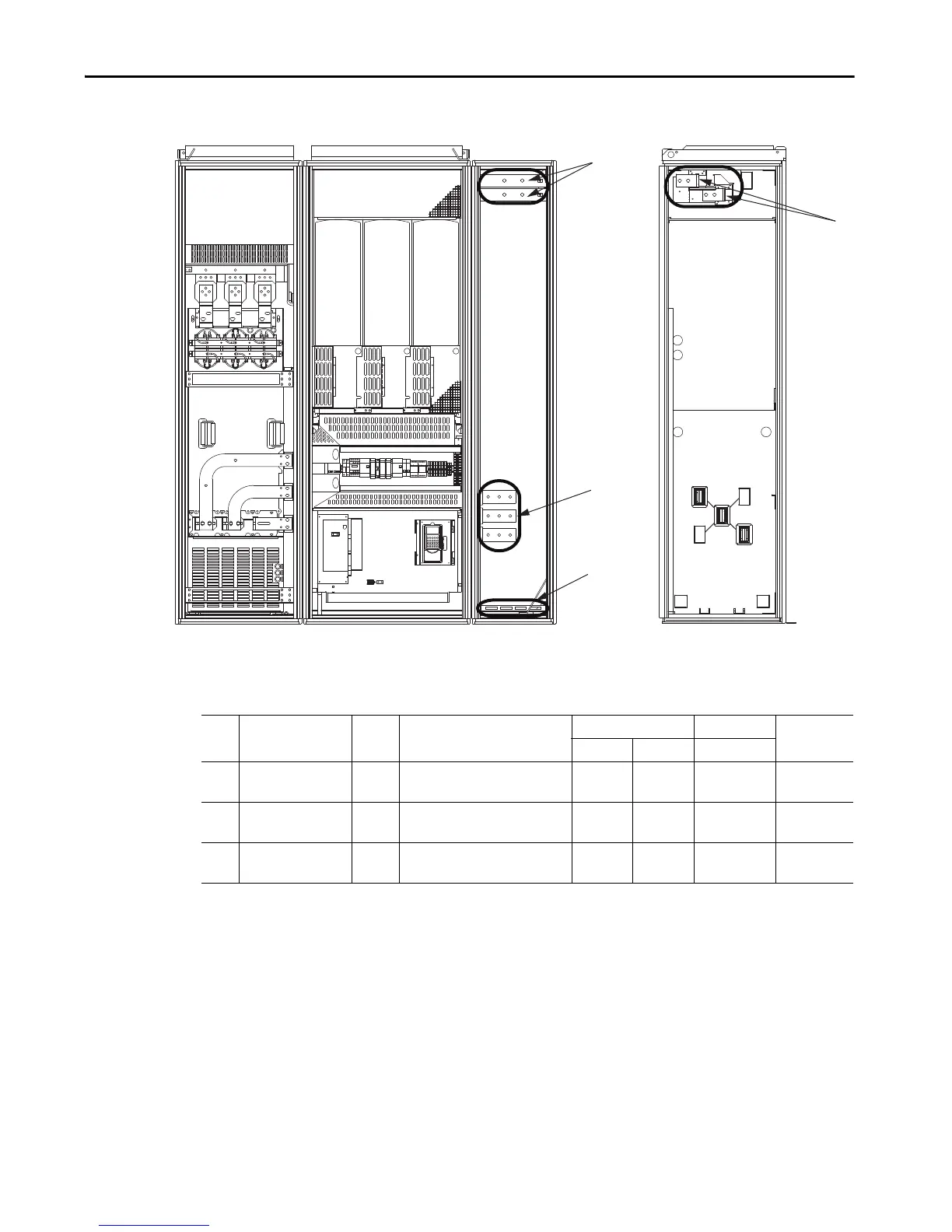
Figure 10 - PowerFlex 700 AFE Frame 13 Power Terminal Locations in IP21 Rittal Enclosure
Table 28 - PowerFlex 700 AFE Frame 13 Power Terminal Specifications in IP21 Rittal Enclosure
Shown with
enclosure doors
removed.
Front View Right Side View
Item Name Frame Description Wire Size Range
(1)
(2)
Tor qu e Term in al Bo lt
Size
(3)
(4)
Maximum Minimum Recommended
1 Input power terminals
L1, L2, L3
(1)
13 Input power 300 mm
2
(600 MCM)
2.1 mm
2
(14 AWG)
70 N•m
(620 lb•in)
M12
2 SHLD terminal, PE,
ground
(3)
13 Terminating point for wiring shields 300 mm
2
(600 MCM)
2.1 mm
2
(14 AWG)
40 N•m
(354 lb•in)
M10
3DC bus
(3)
(DC–, DC+) 13 DC output 300 mm
2
(600 MCM)
2.1 mm
2
(14 AWG)
70 N•m
(620 lb•in)
M12
(1) Maximum/minimum sizes that the terminals accept. These sizes are not recommendations.
(2) Do not exceed maximum wire size. Parallel connections can be required.
(3) These connections are bus bar type terminations and require the use of lug type connectors.
(4) Apply counter-torque to the nut on the other side of terminations when tightening or loosening the terminal bolt to avoid damage to the terminal.

 Loading...


