26 Rockwell Automation Publication 750-UM003D-EN-P - March 2017
Chapter 2 Installation and Wiring
2. Pass the tips of the standoff pins through both boards so that the tip
completely expands.
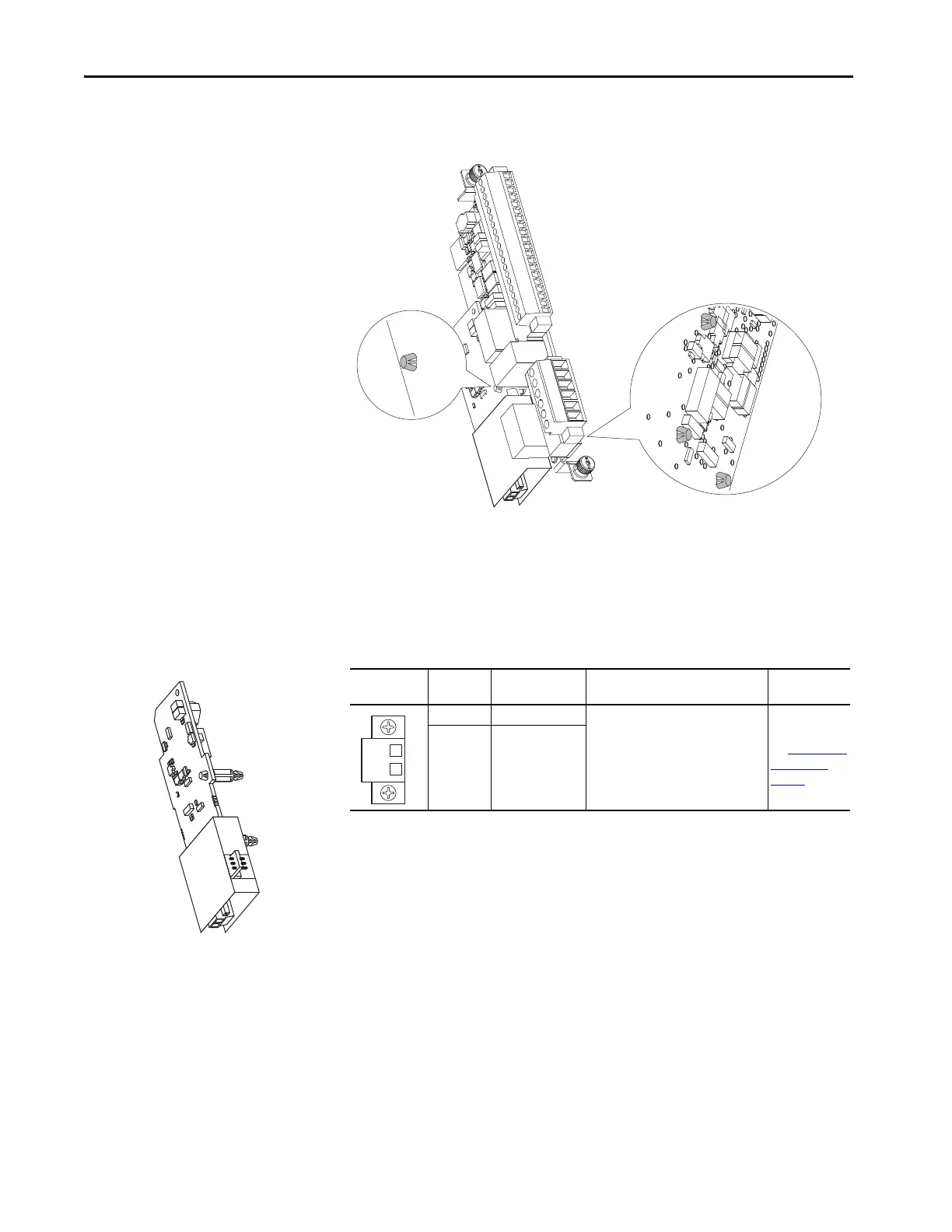
Connect the Thermal Sensor
Wires
Connect the thermal sensor wires to the removable terminal block of the
ATE X option module.
Table 2 - ATEX Terminal Designations
Cabling Requirements
Follow these requirements for thermal sensor wiring to the removable terminal
block of the ATEX option module:
• Use cable duct, conduit, armored cable, or other means to help protect
the thermal sensor wires from damage.
• Use shielded, twisted-pair cable.
Terminal Name Description Related
Parameter
ATEX+ ATEX input (+) Motor protection device input.
Thermostat or PTC-type device.
Polarity can be ignored.
Parameter 41
[ATEX Sts]
See Parameter 41
[ATEX Sts] on
page 39.
ATEX- ATEX input (–)

 Loading...


