44 Rockwell Automation Publication 750-UM003D-EN-P - March 2017
Appendix A Specifications and Certifications
Safety Data
The PFD and PFH values in Ta b le 5 were calculated based on equations in
IEC 61508. This table shows the worst case calculated values for drive frames
1…10 with a proof test interval of 20 years.
These values show the SIL 1 consumption of the ATEX safety function to be
approximately 30%. The safety calculations represent the local ATEX safety
path from the input of the ATEX daughter card to the device that disables
heat-producing power.
Table 5 - PFD and PFH for 20-year Proof Test Interval for Frames 1…10
Environmental Specifications
The installation must comply with all environmental, pollution degree, and
drive enclosure rating specifications required for the operating environment.
IMPORTANT A proof test is not defined in this user manual. A proof test interval of 20
years is used for the calculations here.
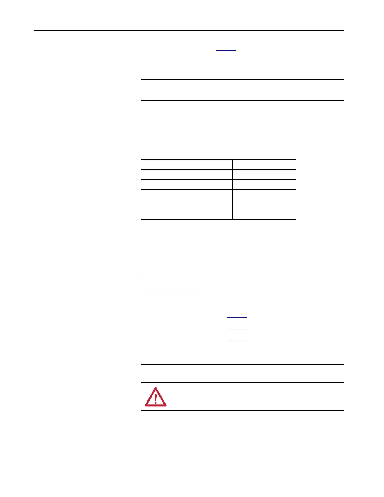
Attribute Value
Safety integrity level (SIL) 1
Hardware fault tolerance (HFT) 0
Mission Time (MT) 20
Probability of failure on demand (PFD) <3.09E-02
Probability of failure per hour (PFH [1/hour]) <3.53E-07
Category Specification
Ambient temperature
For detailed information on environmental, pollution degree, and drive enclosure
rating specifications, see the technical data publication for your drive:
• PowerFlex 750-Series AC Drives Technical Data,
publication 750-TD001
• PowerFlex 750-Series Products with TotalFORCE Control Technical Data,
publication 750-TD100
• PowerFlex 755TM IP00 Open Type Kits Technical Data,
publication 750-TD101
Storage temperature
Shock
Operating
Packaged for shipment
Vibration
Operating
Packaged for shipment
Sinusoidal load
Random secured
Surrounding environment
ATTENTION: A failure to maintain specified ambient temperature can result
in a failure of the safety function.

 Loading...


