8 Rockwell Automation Publication 1746-RM003D-EN-E - May 2019
Preface
– Create intuitive, modern screens for the PanelView™ 5000 graphic
terminals with Studio 5000 View Designer®
– Create and leverage reusable libraries of content for rapid project
development with Application Code Manager
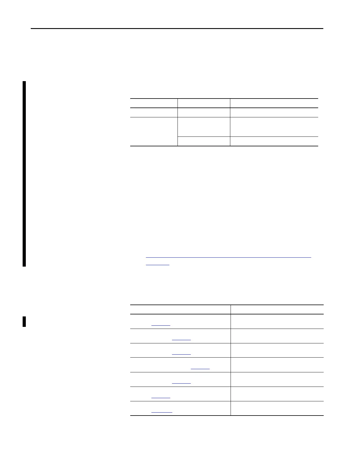
The following CompactLogix controllers are compatible with
Studio 5000 Applications:
• RSLogix 500/RSLogix Micro version 12 or RSLogix Project Migrator
The RSLogix 500/RSLogix Micro version 12 software includes an
integrated SLC to CompactLogix program converter tool. To convert,
simply perform a Save Program As, then select file type as *.ACD, and fill
out the menu prompts.
For older versions of RSLogix 500/RSLogix Micro, the RSLogix Project
Migrator tool is a free, standalone software tool for converting an RSLogix
5 or RSLogix 500 project export file for import into Studio 5000 Logix
Designer application.
The standalone converter tool is available for download at:
http://www.rockwellautomation.com/rockwellautomation/support/
pcdc.page
Additional Resources
These documents contain additional information concerning related products
from Rockwell Automation.
Controllers Cat. No. Studio 5000 Logix Designer® Application
CompactLogix™ 5380 5069-L306ER, 5069-L310ER Version 29.00.00 or later
CompactLogix™ 5370 For CompactLogix 5370
controllers using firmware
revision 21.00.00 or later
Version 21.00.00 or later
1769-L19ER-BB1B Version 28.00.00 or later
Resource Description
SLC 500 Analog Input Module Installation Instructions,
publication 1746-IN006
Installation instructions for the SLC 500 Analog
Input Module (Cat. No. 1746-NI8).
SLC 500 RTD/Resistance Input Module Installation
Instructions, publication 1746-IN007
Installation instructions for the SLC 500 RTD/Resistance
Input Module (Cat. No. 1746-NR8).
SLC 500 RTD/Resistance Input Module Installation
Instructions, publication 1746-IN012
Installation instructions for the SLC 500 RTD/Resistance
Input Module (Cat. No. 1746-NR4).
SLC 500 Thermocouple/mV Analog Input Module
Installation Instructions, publication 1746-IN015
Installation instructions for the SLC 500 Thermocouple/
mV Analog Input Module.
SLC 500 8-Point Analog Output Module Installation
Instructions, publication 1746-IN026
Installation instructions for SLC 500 8-point analog
output modules.
SLC 500 Digital I/O Modules Installation Instructions,
publication 1746-IN027
Installation Instructions for SLC 500 digital I/O modules.
SLC 500 4-Channel Analog I/O Modules User Manual,
publication 1746-UM005
A more detailed description on how to configure the SLC
500 analog I/O modules.

 Loading...


