EasyManuals Logo

Allen-Bradley SLC 500 Installation Instructions

Allen-Bradley SLC 500
48 pages
To Next Page IconTo Next Page
To Previous Page IconTo Previous Page
Page #5 background imageLoading...
Page #5 background image
SLC 500 Digital I/O Modules 5
Publication 1746-IN027D-EN-P - December 2012
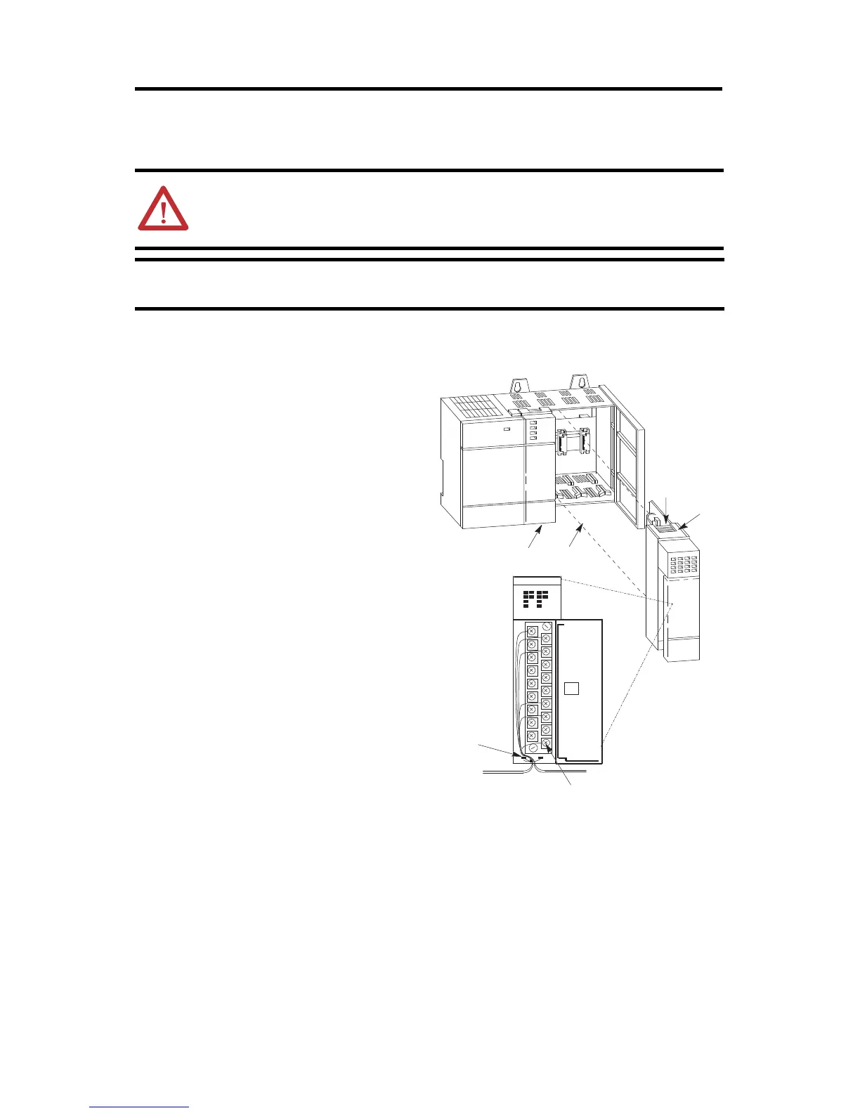
Install and Remove the Module
Follow these steps to install the module:
ATTENTION: Never install, remove, or wire modules with power applied to chassis.
IMPORTANT
The first slot of the chassis is reserved for the processor or the 1747-ASB module.
Slot 1
A
B
D
C
Max 2 mm
2
(14 AWG)
Max 2 wires per terminal
Max torque: 0.9 Nm (8 lb-in.)
1. Disconnect power.
2. Align the circuit board of module
with the chassis card guide. (A)
3. Slide the module into the chassis
until the bottom tabs lock into place.
(B)
4. Route the wires down and away from
the module, securing them with the
wire tie. (C)
5. Cover all unused slots with Card
Slot Filler, catalog number 1746-N2,
to keep the chassis free from debris.
6. To remove the module, press and
hold the module release located on
each self-locking tab, and slide the
module out of the chassis slot. (D)
Module Installation
Aotewell Ltd
www.aotewell.com
Industry Automation
HongKong|UK|China
sales@aotewell.com
+86-755-8660-6182

Other manuals for Allen-Bradley SLC 500

Questions and Answers:

Question and Answer IconNeed help?

Do you have a question about the Allen-Bradley SLC 500 and is the answer not in the manual?

Allen-Bradley SLC 500 Specifications

General IconGeneral
Programming SoftwareRSLogix 500
Communication PortsRS-232, DH-485, DH+
Power Supply120/240V AC or 24V DC
Programming LanguagesLadder Logic
Operating Temperature0°C to 60°C (32°F to 140°F)
Relative Humidity5% to 95% (non-condensing)
Memory4K to 64K words (depending on the processor)

Related product manuals