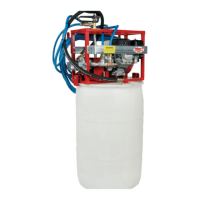
2.1.1 Assembly of Razorback® Power Sprayers to a barrel.
1. After you have uncrated all components received, place the
sprayer (A) on top of the barrel. Using the barrel locks (B)sup-
plied, fasten the sprayer to the barrel.
2. Take the suction tube (C) and the 5’ X 3/4” hose (D) that is
supplied and fasten together. Put the suction tube in the larger
hole of the barrel. Connect opposite end of suction hose to the
3/4” QDC connector located on the sprayer.
3. Take the bypass tube (E) and the 5’ X 1/2” hose (F) that is sup-
plied and fasten together. Put the bypass tube in the smaller
hole of the barrel. Connect opposite end of the bypass hose to
the 1/2” QDC connector located directly below the ow control
valve.
4. Locate the spray wand hose (G). This hose will be the longer of
the three. Connect one end to the spray wand (H) and the op-
posite end to the1/2” QDC connector located on the 90 degree
elbow below the ow control valve on the sprayer.
NOTE: Your sprayer and components may differ from the one
shown in Fig. 1. This will depend on what model you order.
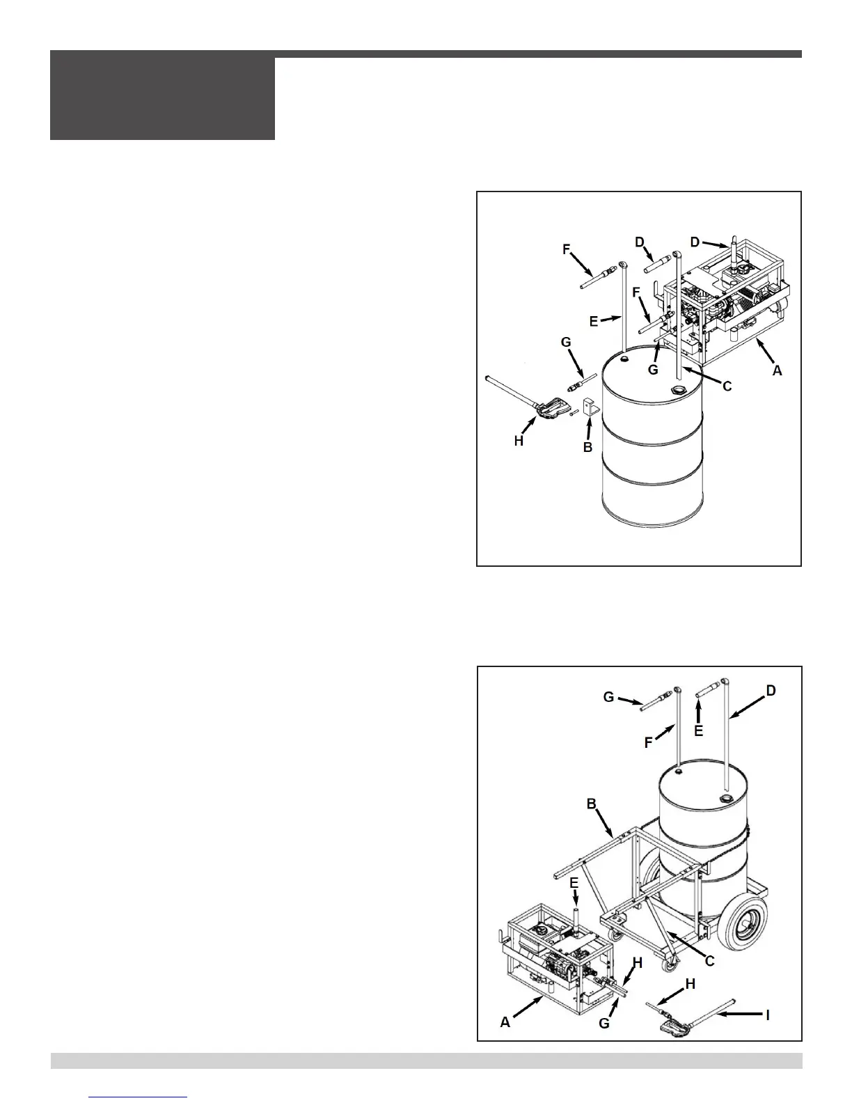
2.1.2 Assembly of Razorback® Power
Sprayers to a Push Cart.
1. After you uncrate all components received, place the sprayer
(A) on the push cart (B). Use the fasteners provided to fasten
the sprayer to the frame. If you are using a 9910 sprayer, you
will need to remove the right hand side, handle to frame, brace
(C) in order to place this sprayer onto the frame. After the 9910
sprayer is fastened to the frame, replace the brace. If you are
using a 6500, 7560, or a 7560XL sprayer, this brace will not
have to be removed.
2. Take the suction tube (D) and the 5’ X 3/4” hose (E) that is
supplied and fasten together. Put the suction tube in the larger
hole of the barrel. Connect opposite end of suction hose to the
3/4” QDC connector located on the sprayer.
Figure 1
Figure 2
Model 9910 Sprayer and Components Shown
2.1 - Sprayer Assembly
SECTION 2
OPERATIONS
038479 Page 28