33
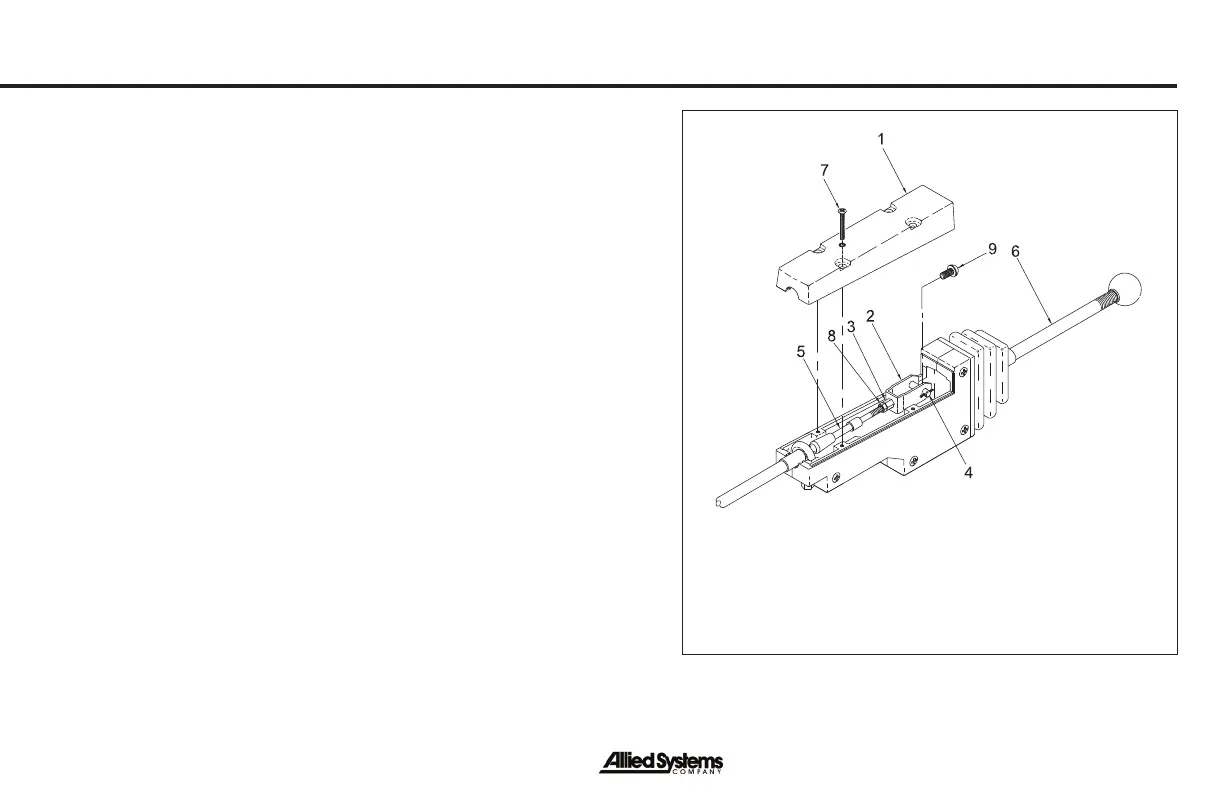
B. See Figure 13. Make sure the positions of the power
control lever are the same as the position indicators on
the decal. Remove the access cover (Item 1) on the
housing to make adjustments. Loosen the jam nut (Item
8) that keeps the tall nut (Item 3) from turning. Remove
the cotter pin and link pin (Item 4) from the clevis (Item
2). Turn the tall nut and clevis to adjust the length of the
control cable (Item 5). Use the link pin and cotter pin to
connect the clevis to the control handle again and check
the operation. When the adjustment is complete, tighten
the jam nut and install the access cover.
Check that the positions of the FREESPOOL control
lever are the same as the position indicators on the decal.
Remove the access cover on the housing. Loosen the nut
that keeps the tall nut from turning. Remove the cotter pin
and link pin from the clevis. Turn the tall nut and clevis to
adjust the length of the control cable. Use the link pin and
cotter pin to connect the clevis to the control handle again
and check the operation. The linkage and cable must be
adjusted so that the FREESPOOL shifter mechanism will
slide the drum pinion gear to both positions. Both positions
have a detent. When the adjustment is complete, tighten
the jam nuts and install the cover.
Figure 13 - Control Cable Adjustments
1. Access Cover
2. Clevis
3. Tall Nut
4. Cotter Pin and Link Pin
5. Control Cable
6. Control Lever
7. Screw
8. Jam Nut
9. Button Head Capscrew
Maintenance