34
C. See Figure 14. This confi guration was last used during
1993.
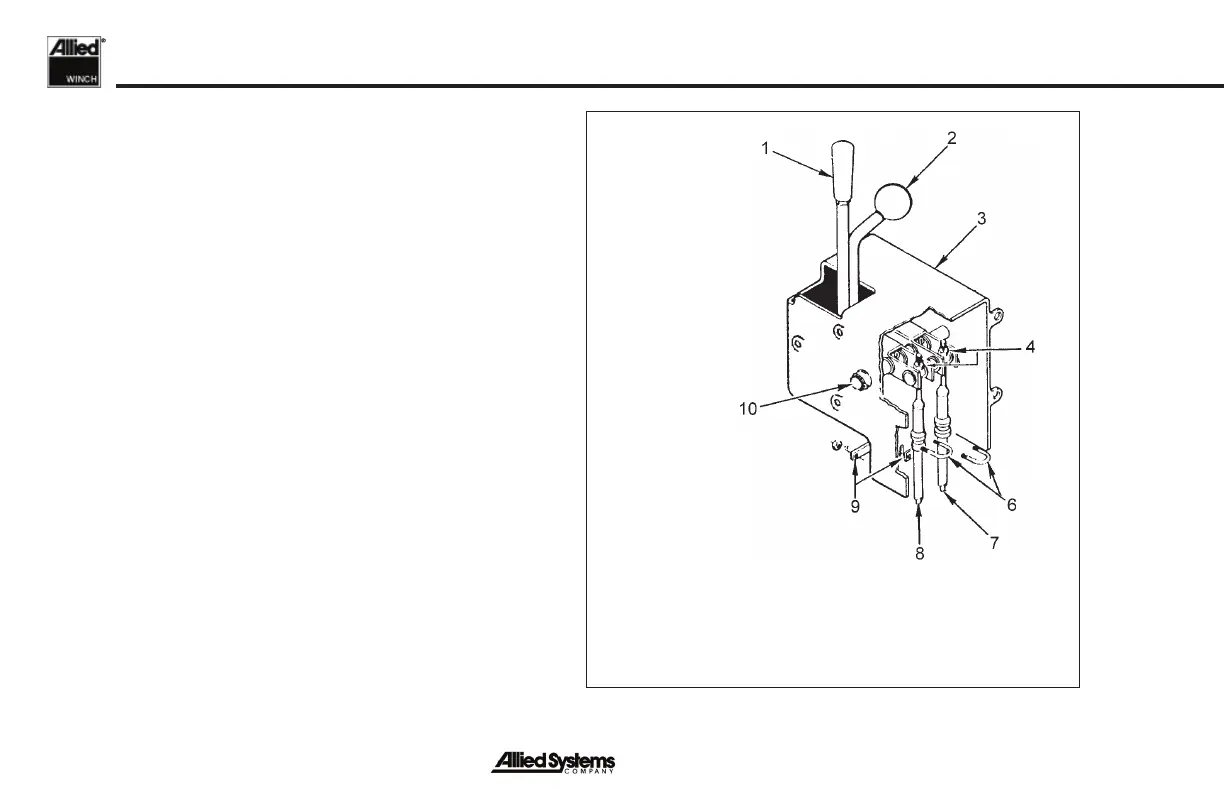
Check the operation of the power control lever (Item 1)
to make sure it moves smoothly and will return to the
BRAKE-ON position. The power control lever will stay in
the BRAKE-OFF position when pushed into the detent
position.
Check that the positions of the power control lever are the
same as the position indicators on the control housing
(Item 3). Loosen the U-bolt (Item 6) that holds the power
control cable (Item 8) in the housing to adjust the control
lever. Make sure the control lever does not hit the
housing at the end of its travel. Check the operation
of the FREESPOOL lever (Item 2) for smooth operation.
Each of the two positions has detent.
Make sure the positions of the FREESPOOL lever
are the same as the position indicators on the control
housing. Loosen the U-bolt that holds the freespool
control cable (Item 7) in the housing to adjust the control
lever. The linkage and cable must be adjusted so that the
FREESPOOL shifter mechanism will slide the drum pinion
gear to both positions. Both positions have a detent.
1. Power Control Lever
2. Freespool Control Lever
3. Housing
4. Locknut
6. U-Bolt
7. Freespool Control Cable
8. Power Control Cable
9. Spacer
10. Pivot Pin
Figure 14 - Control Cable Adjustments