Installation
16
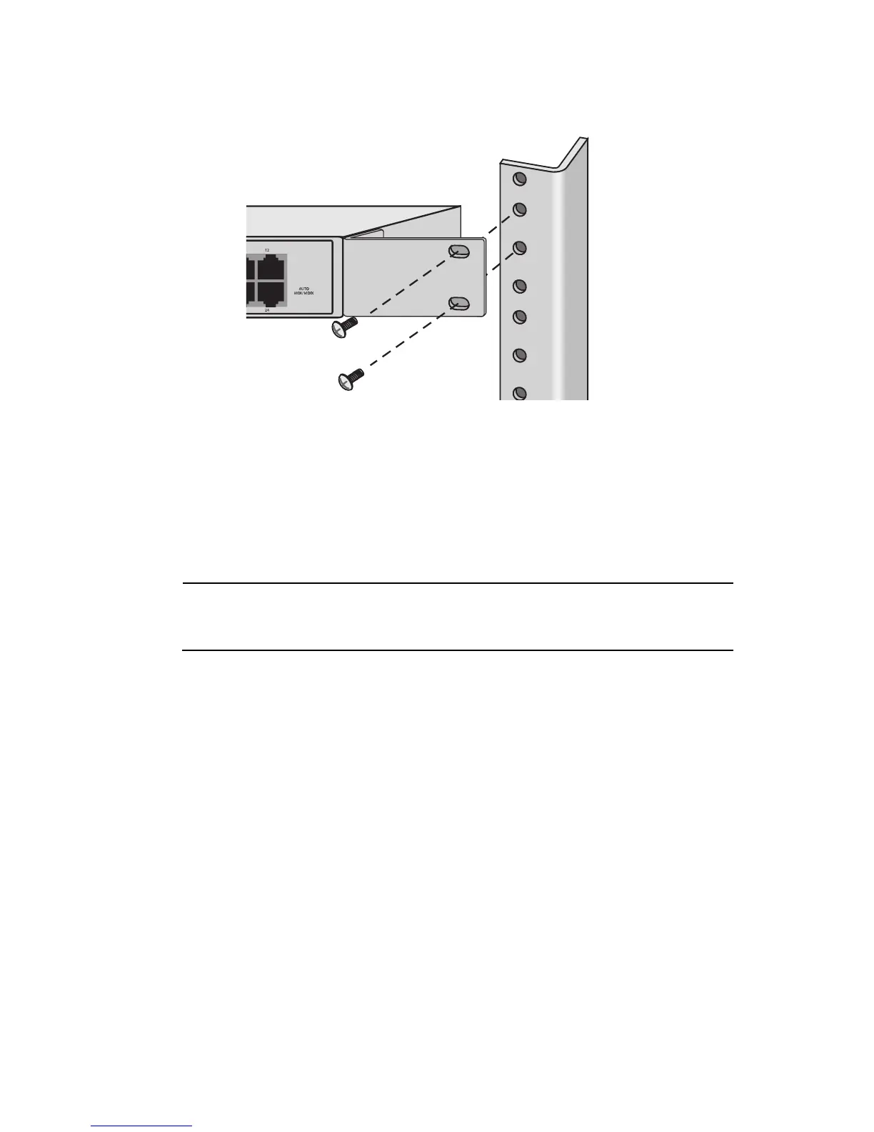
4. Secure the switch to the rack using 2 screws (not provided) for each side as
shown in Figure 7.
Figure 7 Installing the Switch to the Rack
5. Apply power to the switch by plugging one end of the power cord to the
power receptacle and the other end to a power outlet. Verify that the
POWER LED is green. If the LED is OFF, refer to “Troubleshooting” on
page 19.
Note
The switch performs a self-diagnostic test upon power up. This takes
about 20 seconds to complete.
6. Connect the twisted pair cables to a twisted pair ports on the switch and on
the end-nodes.
7. Power ON the end-nodes connected to the switch.
8. Check that the LINK/ACTIVITY LED for each port on the switch is green.
If a LED is OFF, refer to “Troubleshooting” on page 19.
The switch is now ready for use.
 Loading...