AT-FS724L Fast Ethernet Switch Installation Guide
23
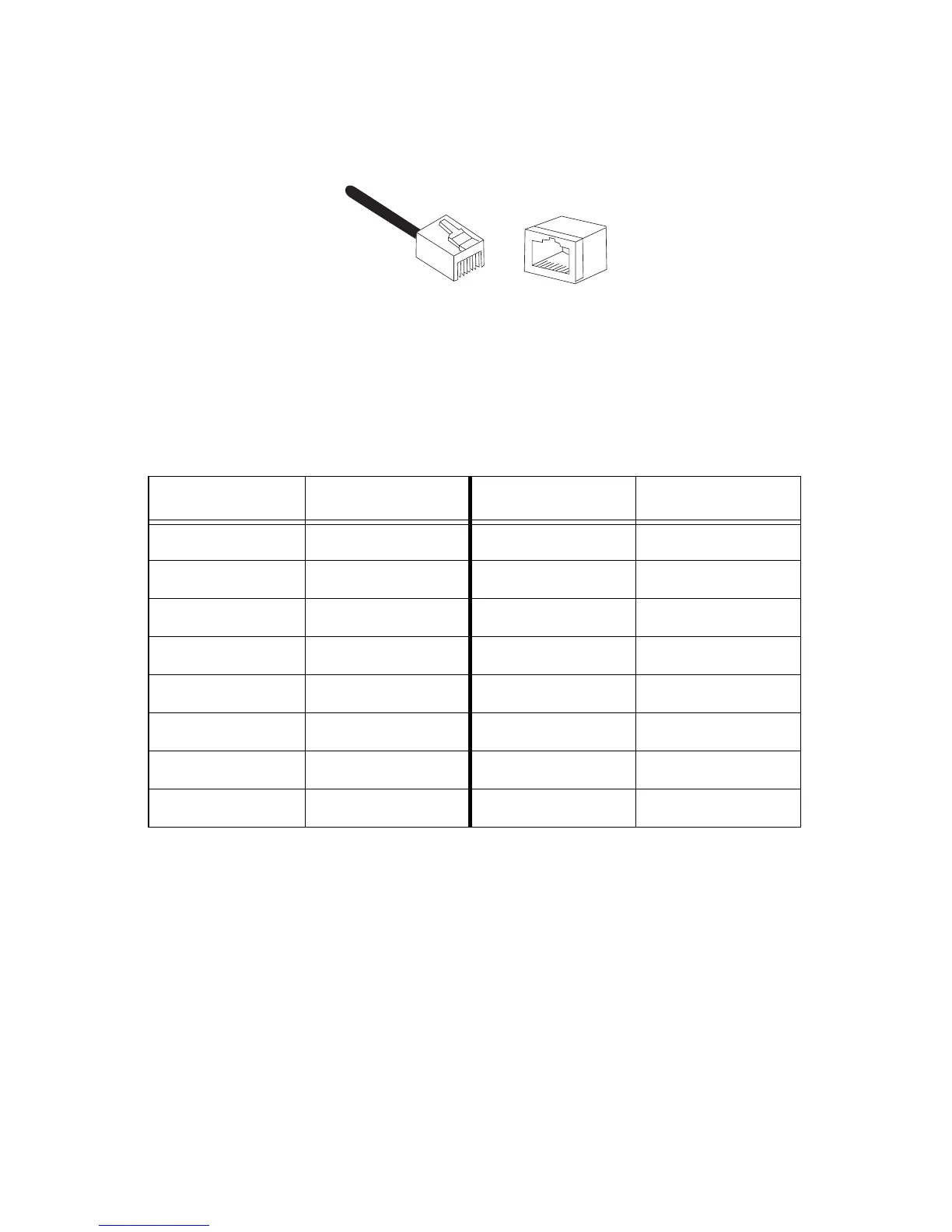
Pinout Assignments
Figure 8 shows the pin assignments of the RJ-45 connector.
Figure 8 RJ-45 Connector
Table 4 lists the 100Base-TX connector pins and their signals when the port is
operating in either MDI or MDI-X configuration.
Table 4 RJ-45 Pin Signals
MDI-X (Default) Signal MDI Signal
1RX+1 TX+
2RX-2 TX-
3 TX+ 3 RX+
4- 4 -
5- 5 -
6 TX- 6 RX-
7- 7 -
8- 8 -
8
8
1
1
 Loading...