AT-GS950/48 Gigabit Ethernet Smart Switch Installation Guide
25
Network Topologies
This section illustrates two network topologies that you can create with the
AT-GS950/48 Gigabit Ethernet Smart switch: a power workgroup and
collapsed backbone. Both types of topologies are described below.
Power
Workgroup
Topology
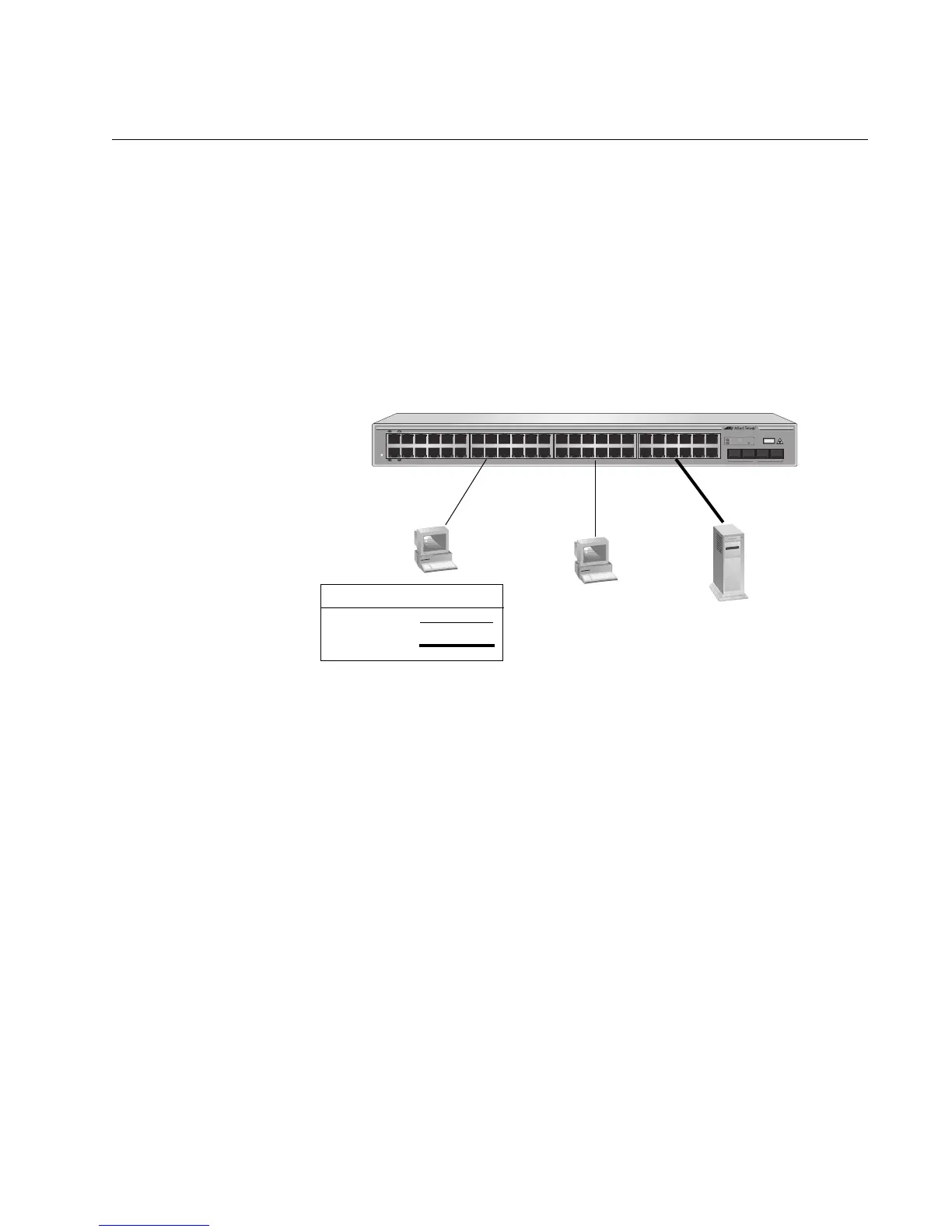
The topology shown in Figure 4 is commonly referred to as a power
workgroup topology. Each workstation or end node is connected directly to
a port on the AT-GS950/48 Gigabit Ethernet Smart switch. Each end node
has a dedicated data link to the switch for best performance and reliability.
The devices can operate at 100 Mbps or 1000 Mbps.
Figure 4. Power Workgroup Topology
1075
1 3 5 7 9 11 131517192123 252729313335 37 39414345R47R
2 4 6 8 10 12 14 16 18 20 22 24 26 28 30 32 34 36 38 40 42 44 46R 48R
45 46 47 48
POWER
CLASS 1
LASER PRODUCT
AT-GS950/48
48 Port 10/100/1000 Mbps WebSmart Switch with 4 Combo SFP Ports
LINK
1000M
ACT
100M 10M
PORT ACTIVITY
SFP
Legend
100 Mbps
1000 Mbps

 Loading...


