508228-01 Issue 2136 Page 19 of 41
It is recommended that vertical suction risers not be up-
sized. Proper oil return to the compressor should be
maintained with suction gas velocity.
Filter Drier
The lter drier is very important for proper system operation
and reliability. If the drier is shipped loose, it must be
installed by the installer in the eld. Unit warranty will be
void, if the drier is not installed.
Installation of Line Sets
DO NOT fasten liquid or suction lines in direct contact with
the oor or ceiling joist. Use an insulated or suspension
type of hanger. Keep both lines separate, and always
insulate the suction line. Liquid line runs (30 feet or more)
in an attic will require insulation. Route refrigeration line
sets to minimize length.
DO NOT let refrigerant lines come in direct contact with
foundation. When running refrigerant lines through the
foundation or wall, openings should allow for a sound
and vibration absorbing material to be placed or installed
between tubing and foundation. Any gap between
foundation or wall and refrigerant lines should be lled with
a vibration damping material.
If ANY refrigerant tubing is required to be buried by state
or local codes, provide a 6 inch vertical rise at service
valve.
CAUTION
Installation into an Existing R-22 System
If the unit will be installed in an existing system that uses
an indoor unit or line sets charged with R-22 refrigerant,
installer must perform the following procedures to convert
the system to an R-410A system.
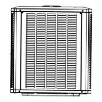
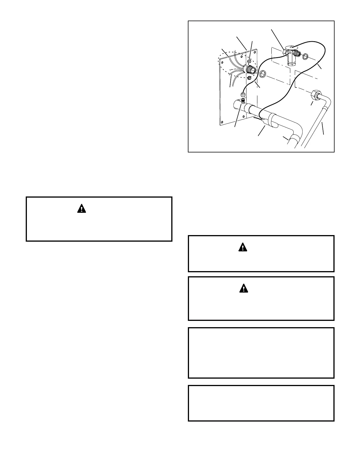
Remove Existing Expansion Valve
1. On fully cased coils, remove the coil access and
plumbing panels.
2. Remove any shipping clamps from the liquid line and
distributor assembly.
3. Disconnect the equalizer line from the check expansion
valve equalizer line tting on the vapor line.
4. Remove the vapor line sensing bulb.
5. Disconnect the liquid line from the check expansion
valve at the liquid line assembly.
6. Disconnect the check expansion valve from the liquid
line orice housing. Take care not to twist or damage
distributor tubes during this process.
7. Remove and discard check expansion valve and the
two Teon® rings (see Figure 6).
8. Use a eld-provided tting to temporarily reconnect the
liquid line to the indoor unit’s liquid line orice housing.
SENSING
LINE
TWO-PIECE PATCH PLATE
(UNCASED COIL ONLY)
VAPOR
LINE
DISTRIBUTOR
ASSEMBLY
DISTRIBUTOR
TUBES
LIQUID
LINE
MALE EQUALIZER
LINE FITTING
EQUALIZER
LINE
EXPANSION
VALVE
TEFLON
®
RING
STUB END
TEFLON
®
RING
SENSING BULB
LIQUID LINE
ORIFICE
HOUSING
LIQUID LINE
ASSEMBLY WITH
BRASS NUT
Figure 6. Remove Existing Expansion Valve
(uncased coil shown)
Flushing Line Sets
If the unit will be installed in an existing system that uses
an indoor unit or line sets charged with R-22 refrigerant,
installer must perform the following ushing procedure.
NOTE: Existing system components (including line set
and indoor coil) must be an AHRI match with the unit in
order to fulll unit warranty requirements.
Refrigerant must be reclaimed in accordance with
national and local codes.
WARNING
Do NOT attempt to ush and re-use existing line sets
or indoor coil when the system contains contaminants
(i.e., compressor burn out).
CAUTION
“Clean refrigerant” is any refrigerant in a system that
has not had compressor burnout. If the system has
experienced burnout, it is recommended that the
existing line set and indoor coil be replaced.
NOTE
In lieu of R-410A, an industry-standard ushing agent
may also be used.
NOTE
 Loading...