508155-01Issue 2108Page 22 of 49
Troubleshooting Motor Windings
Ensure that motor windings are not damaged by performing
the following tests:
NOTE: If your ohm meter is not an auto-ranging type, set
it to the highest ohm scale (100k ohms or greater) before
performing tests.
Scale
Measurement Range
in Words in ohms
2 M two megohm-two million ohms 0 - 2,000,000
200 K two hundred kilo-ohm-two
hundred thousand ohms
0 - 200,000
20 K twenty kilo-ohm-twenty thousand
ohms
0 - 20,000
2 K two kilo-ohm two-thousand ohms 0 - 2,000
200 two hundred ohms 0 - 200
Table 13. Ohm Meter Range
Figure 10.
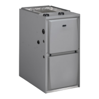
TEST A
Measure the resistance between each of the three motor
leads (3-pin plug) and the unpainted part of the end shield.
If the winding resistance to ground is <100k ohms, replace
the motor and control module. If the resistance to ground
is >100k, the motor windings are ne. Proceed to Test B.
Figure 11. Test A
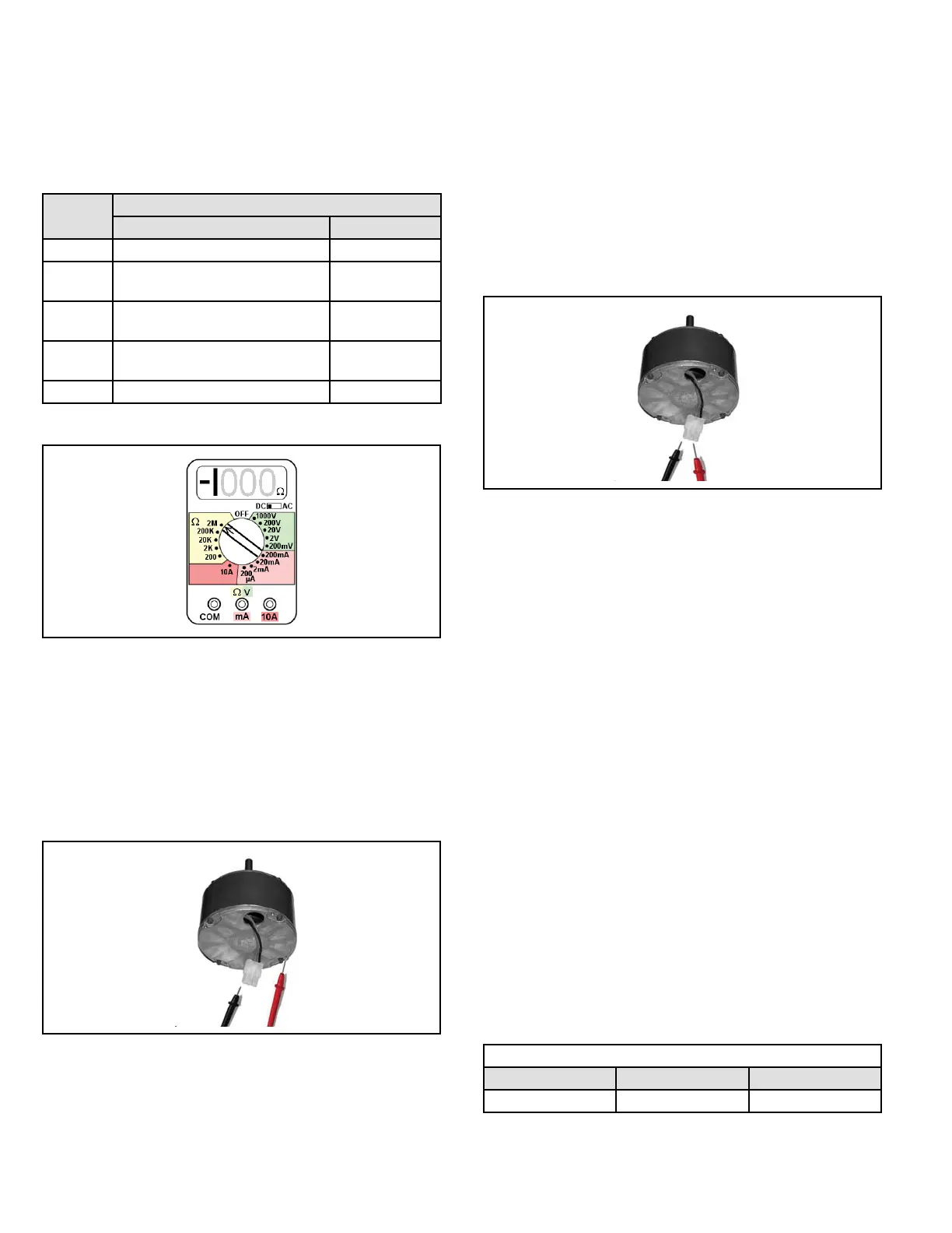
TEST B
Use an ohmmeter to measure the motor phase-to-phase
resistance by checking these combinations of the the 3-pin
motor plug. For the purpose of this test, start at either end
of the connector as lead 1.
1. The lead-to-lead resistance across any two leads
should be less than 20 ohms.
2. Each lead-to-lead resistance should be the same.
If the measured resistance is greater than 20 ohms, replace
the motor and control module.
Figure 12. Test B
Heating Components
Ignitor
The ignitor is made of durable silicon nitride. Ignitor
longevity is enhanced by controlling voltage to the ignitor.
The integrated control provides a regulated 120 volts to the
ignitor for a consistent ignition and long ignitor life. Ohm
value should be 39 to 70. See Figure 14 for ignitor location
and Figure 13 for ignitor check out.
NOTE: The A80US2V furnace contains electronic
components that are polarity sensitive. Make sure that the
furnace is wired correctly and is properly grounded.
Flame Sensor
A ame sensor (Figure 14) is located on the left side of
the burner support. The sensor is mounted on the ame
rollout plate and the tip protrudes into the ame envelope
of the left-most burner. The sensor can be removed for
service without removing any part of the burners. During
operation, ame is sensed by current passed through the
ame and sensing electrode. The control allows the gas
valve to remain open as long as ame signal is sensed. To
check ame sense signal use the push-button found on the
integrated control and go to Field Test Mode. The menu
will display the ame signal. See Table 14 for ame signal.
Flame Signal in Microamps
Normal Low Drop Out
2.6 or greater 2.5 or less 1.1
Table 14.