508155-01 Issue 2108 Page 25 of 49
Primary Limit Control
The primary limit (S10) is located in the heating vestibule
panel. When excess heat is sensed in the heat exchanger,
the limit will open. If the limit is open, the furnace control
energizes the supply air blower and closes the gas valve.
The limit automatically resets when unit temperature
returns to normal. The switch must reset within three
minutes or the control will go into Watch guard for one
hour. The switch is factory set and cannot be adjusted. The
switch may have a dierent set point for each unit model
number.
Secondary Limit Controls
The secondary limit (S21) is located in the blower
compartment on the back side of the blower housing.
A80US2V units require two secondary limits. When excess
heat is sensed in the blower compartment, the limit will
open. If the limit is open, the furnace control energizes
the supply air blower and closes the gas valve. The limit
automatically resets when unit temperature returns to
normal. The switch must reset within three minutes or the
control will go into Watch guard for one hour. The switch is
factory set and cannot be adjusted.
Combustion Air Inducer
All A80US2V units use a two-stage combustion air inducer
to move air through the burners and heat exchanger during
heating operation. The blower uses a 120VAC motor.
The motor operates during all heating operation and is
controlled by integrated control control A92. The inducer
also operates for 15 seconds before burner ignition (pre-
purge) and for 5 seconds after the gas valve closes (post-
purge). The inducer operates on low speed during rststage
heat, then switches to high speed for second stage heat.
A proving switch connected to the combustion air inducer
orice plate is used to prove inducer operation. The
combustion air inducer orice will be dierent for each
model. See Table 15 for orice sizes. The switch monitors
air pressure in the inducer housing. During normal
operation, the pressure in the housing is negative. If
pressure becomes less negative (signifying an obstruction)
the proving switch opens. When the proving switch opens,
the furnace control (A92) immediately closes the gas valve
to prevent burner operation.
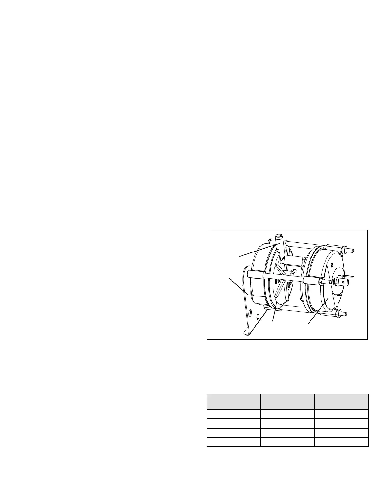
Combustion Air Inducer Prove Switch
A80US2V series units are equipped with a dual combustion
air proving switch (rst and second stage) located on the
combustion air inducer orice bracket. See Figure 15. The
switch is connected to the combustion air inducer housing
by means of a exible silicone hose. It monitors negative
air pressure in the combustion air inducer housing.
The switches are a single-pole single-throw proving
switch electrically connected to the integrated control.
The purpose of the switch is to prevent burner operation
if the combustion air inducer is not operating or if the ue
becomes obstructed.
On heat demand (rst or second stage) the switch senses
that the combustion air inducer is operating. It closes a
circuit to the integrated control when pressure inside the
combustion air inducer decreases to a certain set point.
Set points vary depending on unit size. See Table 15.
The pressure sensed by the switch is negative relative
to atmospheric pressure. If the ue becomes obstructed
during operation, the switch senses a loss of negative
pressure (pressure becomes more equal with atmospheric
pressure) and opens the circuit to the furnace control and
gas valve. A bleed port on the switch allows relatively
dry air in the vestibule to purge switch tubing, to prevent
condensate build up.
Figure 15.
Tap
High Fire
Switch
Low Fire
Switch
Bracket
NOTE: The switch is factory set and is not eld adjustable.
It is a safety shut-down control in the furnace and must
not be by-passed for any reason. If switch is closed or
bypassed, the control will not initiate ignition at start up.
Unit
Set Point
Low Heat
Set Point
High Heat
-070 0.25 0.60
-090 0.30 0.68
-110 0.30 0.68
-135 0.30 0.75
Table 15. 0 - 4500’