508155-01 Issue 2108 Page 7 of 49
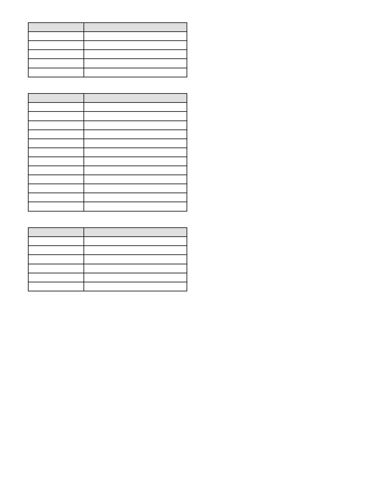
Pin # Function
1 Ignitor
2 Combustion Air Inducer High Speed
3 Combustion Air Inducer Low Speed
4 Combustion Air Inducer Neutral
5 Ignitor Neutral
Table 1. Control 5-Pin Terminal Designation
Pin # Function
1 Gas Valve Second Stage
2 Second Stage Prove Switch
3 Rollout Switch In
4 Ground
5 24V Hot
6 Primary Limit In
7 Gas Valve First Stage
8 Gas Valve Common
9 24V Neutral
10 Ground
11 Rollout Switch Out
12 First Stage Prove Switch
Table 2. Control 12-Pin Terminal Designation
Pin # Function
1 Data Input From Motor
2 Common
3 Not Used
4 Data Output To Motor
5 5 Volt Bias Supply
6 Not Used
Table 3. Control 6-Pin Terminal Designation
Electronic Ignition
At the beginning of the heat cycle the integrated control
monitors the rst stage and second stage combustion air
inducer prove switch. The control will not begin the heating
cycle if the rst stage prove switch is closed (by-passed).
Likewise the integrated control will not begin the second
stage heating cycle if the second stage prove switch is
closed, and will remain in rst stage heat. However, if the
second stage prove switch closes during the rst stage
heat pre-purge, the control will allow second stage heat.
Once the rst stage prove switch is determined to be open,
the combustion air inducer is energized on low (rst stage)
heat speed. When the dierential in the prove switch is
great enough, the prove switch closes and a 15-second
pre-purge begins.
NOTE: During abnormal conditions such as low supply
voltage or low outdoor temperatures and the low re
pressure switch does not close, the combustion air inducer
will switch to high re. After a 15 second pre-purge the
high re pressure switch will close and the unit will begin
operation on high re. After 10 to 20 seconds of high re
operation the unit will switch to low re
After the 15-second pre-purge period, the ignitor warms
up for 20 seconds after which the gas valve opens for a
4-second trial for ignition. The ignitor remains energized
during the trial until ame is sensed. If ignition is not proved
during the 4-second period, the control will try four more
times with an inter purge and warm-up time between trials
of 35 seconds. After a total of ve trials for ignition (including
the initial trial), the control goes into Watchguard-Flame
Failure mode. After a 60-minute reset period, the control
will begin the ignition sequence again.
Two Stage Operation / Thermostat Selection
DIP Switch
The control can be utilized in two modes: SINGLE-STAGE
thermostat or TWO-STAGE thermostat. The thermostat
selection is made using a DIP switch and must be positioned
for the particular application. DIP switch 1, labeled T”STAT
HEAT STAGE is factory-set in the OFF position for use
with a two-stage thermostat. Move the DIP switch to ON
for use with a single stage thermostat.
While in the single-stage thermostat mode, the burners will
always re on rst-stage heat. The combustion air inducer
will operate on low speed and indoor blower will operate on
low heat speed. The unit will switch to second stage heat
after a “recognition period”. DIP switch 2, labeled SECOND
STAGE DELAY, is factory set in the OFF position for a 7
minute recognition period. The switch can be moved to the
ON position for a 12 minute recognition period, after which
time the unit will switch to secondstage heat.
While in the two-stage thermostat mode, the burners will
re on rst-stage heat. The combustion air inducer will
operate on low speed and indoor blower will operate on low
heat speed. The unit will switch to second-stage heat on
call from the indoor thermostat. If there is a simultaneous
call for rst and second stage heat, the unit will re an
rst stage heat and switch to second stage heat after 30
seconds of operation. See Sequence of Operation ow
charts in the back of this manual for more detail.