508433-01Issue 2345Page 22 of 70
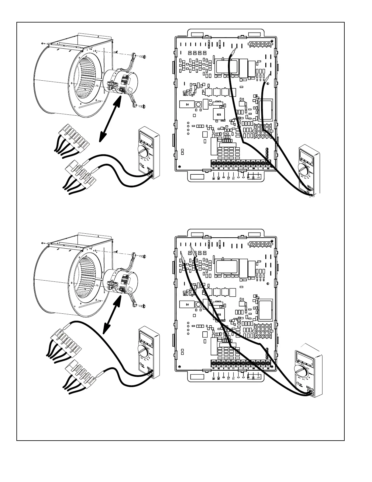
Figure 10.
1
2
3
4
5
C
L
G
N
Multi−Meter
(set to VAC)
P48
P49
24
Test 1
Test 2
Test 3 (if necessary)
Test 4 (if necessary)
1
2
3
4
5
C
L
G
N
Multi−Meter
(set to VAC)
P48
P49
12
0
12
0
Multi−Meter
(set to VAC)
12
0
12
0
24
Multi−Meter
(set to VAC)
Turn on power to unit. Check for 120 volts across terminals
“L” and “N” on input plug P48. If voltage is present continue
to test 2. If voltage is not present, problem may be upstream
of plug P48 and proceed to test 3.
Check for 120 volts across terminals “L1” and “Neutrals” on
the integrated control. If voltage is present, problem is with
the harness. If voltage is not present problem may be may
be with the integrated control.
Switch thermostat to CONTINUOUS FAN MODE. Check for
24 volts across terminal “C” on input plug P48 and speed
tap used for continuous fan (1, 2, 3, 4 or 5) on input plug
P49. If 24 volts is not present, problem may be upstream of
plug P49. Proceed to test 4.
Check for 24 volts across terminals “24 COM” and the
“active speed trap” on the integrated control. If voltage is
present, problem is with the harness. If voltage is not
present, problem may be may be with the integrated
control.