508433-01Issue 2345Page 2 of 70
Technical Specications - A97UH2E
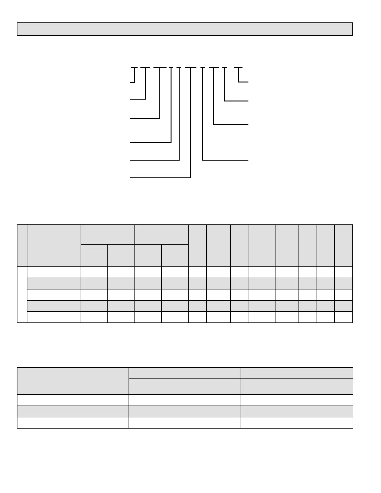
MODEL NUMBER GUIDE
PHYSICAL AND ELECTRICAL DATA
Model
1st Stage 2nd Stage
AFUE
(ICUS)
Nom. Cooling
Capacity
(tons)
Gas Inlet
(in.)
Volts / Hz /
Phase
Min. Time
Delay Breaker
or Fuse
Nominal F.L.A.
Trans.
(V.A.)
Approx. Weight
(lbs.)
Input
(Btuh)
Output
(Btuh)
Input
(Btuh)
Output
(Btuh)
Upow / Horizontal
A97UH2E030B08S 20,000 19,000 30,000 29,000 97.0 2 1/2 120-60-1 15 6.8 40 120
A97UH2E045B12S 29,000 28,000 44,000 43,000 97.0 3 1/2 120-60-1 15 6.8 40 121
A97UH2E070B12S 43,000 42,000 66,000 65,000 97.0 3 1/2 120-60-1 15 6.8 40 129
A97UH2E090C16S 57,000 55,000 88,000 85,000 97.0 4 1/2 120-60-1 15 8.4 40 151
A97UH2E110C20S 72,000 71,000 110,000 108,000 97.0 5 1/2 120-60-1 15 10.9 40 160
Note: For vent length and clearances to combustibles, please reference installation instructions.
Major Revision Code
Numeric Code
Heat Exchanger
S = Stainless Steel Heat
Exchanger
Nom. CFM x 100
08 = 2 Ton add on cooling
12 = 3 Ton add on cooling
16 = 4 Ton add on cooling
20 = 5 Ton add on cooling
Cabinet Width
B = 17.5” width
C = 21.0” width
D = 24.5” width
A
Flagship
AFUE
97 = 97% Efficency
Configuration
UH = Upflow/Horizontal
DF = Downflow
Stages
2 = Two Stage
Blower Drive
E = High Efficiency Motor
BTUH
Heating Input x 1000
A 97 UH 2 E 110 C 20 S -01
FILTER REQUIREMENT DATA
Airow Descriptor
Disposable Filters Cleanable Filters
Minimum Area
(sq. in.)
Minimum Area
(sq.in.)
12 576 288
16 768 384
20 960 480
1. The Airflow Descriptor is the two digits following the “B”, “C”, or “D” in the model number; e.g. “20” is the Airflow Descriptor.
2. Areas shown for permanent filters are based on filters rated at 600 feet per minute face velocity.