508433-01 Issue 2345 Page 51 of 70
4. Move gas valve switch to OFF.
5. Replace the access panel.
Failure To Operate
If the unit fails to operate, check the following:
1. Is the thermostat calling for heat?
2. Are access panels securely in place?
3. Is the main disconnect switch closed?
4. Is there a blown fuse or tripped breaker?
5. Is the lter dirty or plugged? Dirty or plugged lters will
cause the limit control to shut the unit o.
6. Is gas turned on at the meter?
7. Is the manual main shut-o valve open?
8. Is the internal manual shut-o valve open?
9. Is the unit ignition system in lockout? If the unit locks
out again, inspect the unit for blockages.
Heating System Service Checks
C.S.A. Certication
All units are C.S.A. design certied without modications.
Refer to the A97UH2E Operation and Installation
Instruction.
Gas Piping
If a exible gas connector is required or allowed by
the authority that has jurisdiction, black iron pipe shall
be installed at the gas valve and extend outside the
furnace cabinet. The exible connector can then be
added between the black iron pipe and the gas supply
line.
CAUTION
Do not over torque (800 in-lbs) or under torque (350
in-lbs) when attaching the gas piping to the gas valve.
WARNING
Gas supply piping should not allow more than 0.5” W.C.
drop in pressure between gas meter and unit. Supply gas
pipe must not be smaller than unit gas connection.
Compounds used on gas piping threaded joints should be
resistant to action of liqueed petroleum gases.
Testing Gas Piping
In case emergency shutdown is required, turn o the
main shut-o valve and disconnect the main power to
unit. These controls should be properly labeled by the
installer.
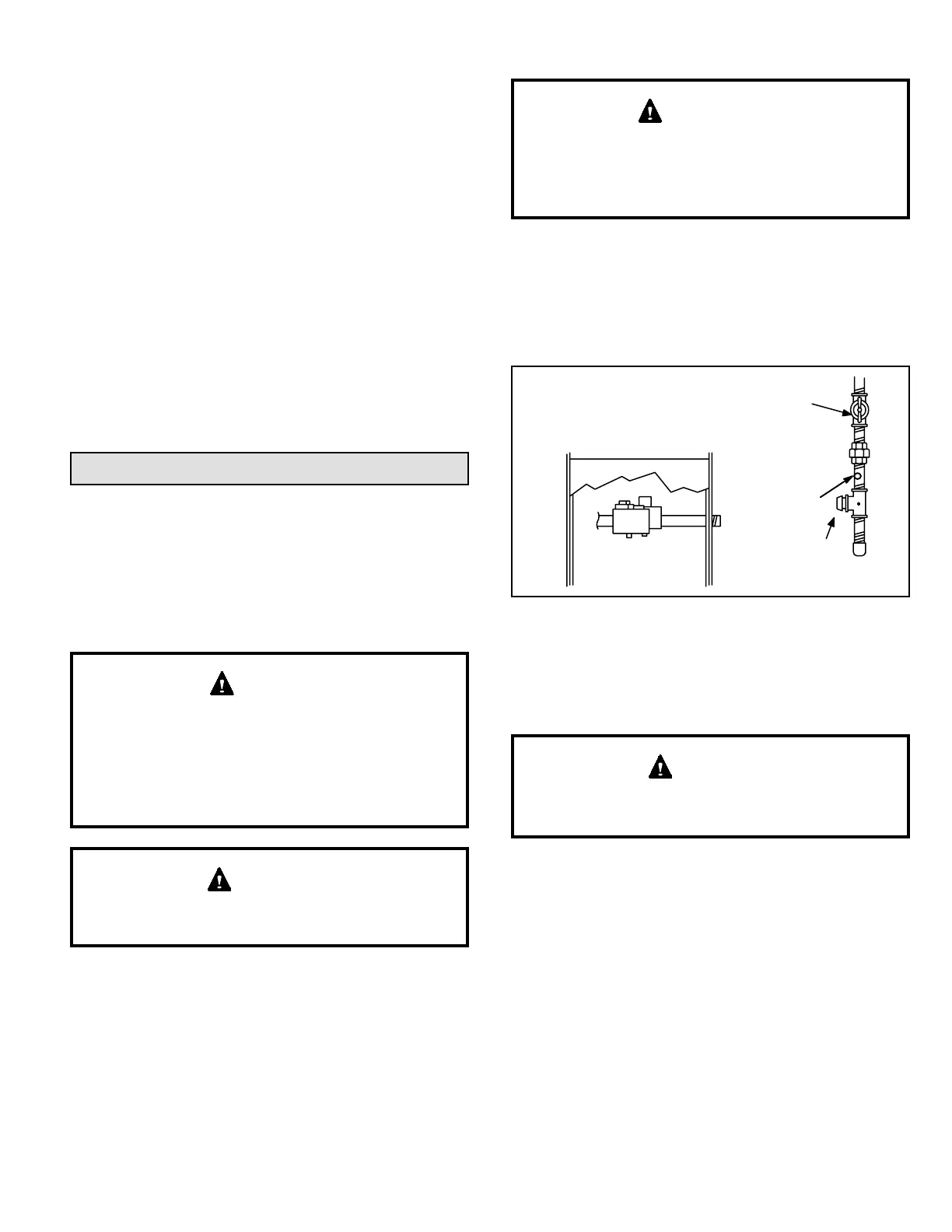
IMPORTANT
When pressure testing gas lines, the gas valve must be
disconnected and isolated. Gas valves can be damaged
if subjected to more than 0.5 psig (14” W.C.). See Figure
51. If the pressure is greater than 0.5psig (14”W.C.), use
the manual shut-o valve before pressure testing to isolate
furnace from gas supply.
Figure 51.
MANUAL MAIN SHUT-OFF VALVE
WILL NOT HOLD TEST PRESSURE
IN EXCESS OF 0.5 PSIG (14”W.C.)
GAS VALVE
CAP
1/8 NPT PLUG
When checking piping connections for gas leaks, use
preferred means. Kitchen detergents can cause harmful
corrosion on various metals used in gas piping. Use of a
specialty Gas Leak Detector is strongly recommended.
Do not use matches, candles, ame or any other source
of ignition to check for gas leaks.
WARNING
Testing Gas Supply Pressure
An inlet post located on the gas valve provides access to
the supply pressure. See Figure 50. Back out the 3/32 hex
screw one turn, connect a piece of 5/16 tubing and connect
to a manometer to measure supply pressure. See Table 18
for supply line pressure.
Manifold Pressure Measurement
A manifold pressure post located on the gas valve provides
access to the manifold pressure. See Figure 50. Back out
the 3/32 hex screw one turn. Follow the steps below and
use Figure 52 as a reference. Gas manifold Kit 10L34
provides additional components if needed.