508433-01Issue 2345Page 52 of 70
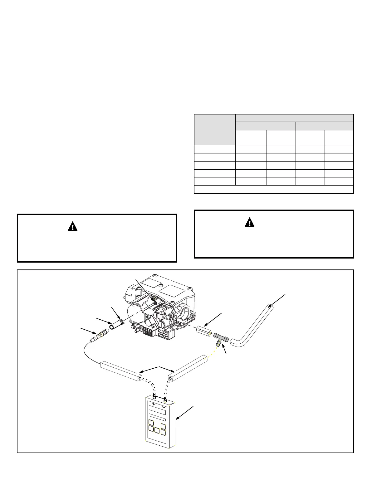
1. Connect the 5/16” round tubing to the manifold post.
Secure with the clamp.
2. Connect the reducer tting to the 5/16” round tubing
followed by a piece of 10” length square tubing.
3. Connect the other end of the square tubing to the “+”
positive side of the measuring device.
4. Take the 2” length square tubing, tee, 10” length of
square tubing and tee into the gas valve regulator vent
hose. Connect to the measuring device negative “-”
side.
5. Ignite unit on low re and let run for 5 minutes to allow
for steady state conditions.
6. After allowing unit to stabilize for 5 minutes, record
manifold pressure and compare to value given in
Table 18.
7. If necessary, make adjustments. Figure 50 shows
location of high re and low re adjustment screws.
8. Repeat steps 5, 6 and 7 on high re. See values in
Table 18.
9. Shut unit o and remove manometer as soon as an
accurate reading has been obtained.
10. Start unit and perform leak check. Seal leaks if found.
For safety, connect a shut-o valve between the
manometer and the gas tap to permit shut o of gas
pressure to the manometer.
IMPORTANT
Gas Flow (Approximate)
Furnace should operate at least 5 minutes before checking
gas ow. Determine time in seconds for two revolutions of
gas through the meter. (Two revolutions assures a more
accurate time.) Divide by two and compare to time in Table
16. If manifold pressure matches Table 18 and rate is
incorrect, check gas orices for proper size and restriction.
Remove temporary gas meter if installed.
NOTE: To obtain accurate reading, shut o all other gas
appliances connected to meter.
Capacity
Seconds for One Revolution
Natural LP
1 cu ft
Dial
2 cu ft
Dial
1 cu ft
Dial
2 cu ft
Dial
-30 120 240 300 600
-45 80 160 200 400
-70 55 110 136 272
-90 41 82 102 204
-110 33 66 82 164
Natural-1000 btu/cu ft LP-2500 btu/cu ft
Table 16. Gas Meter Clocking Chart
For safety, shut unit o and remove manometer as soon
as an accurate reading has been obtained. Take care to
replace pressure tap plug.
IMPORTANT
Manifold Post
Clamp
5/16” Round
Hose
Reducer
Fitting
10” Long
Square
Tubing
2” Long
Square Tubing
Tee
Gas Valve Regulator
Vent Hose
(to burner box)
Measuring Device
Figure 52. Manifold Pressure Check Setup