8
VM 623.0004 GB/07.00 – Ident–Nr. 550 298
If a height, lateral or angle offset is detected between
the two coupling halves, the drive motor should be re–
aligned such that the coupling halves are flush with
each other (level out with flat packing shims as neces–
sary).
The gap between the two coupling halves must be the
same all round the circumference of the coupling. The
specified gap is shown in the installation diagram.
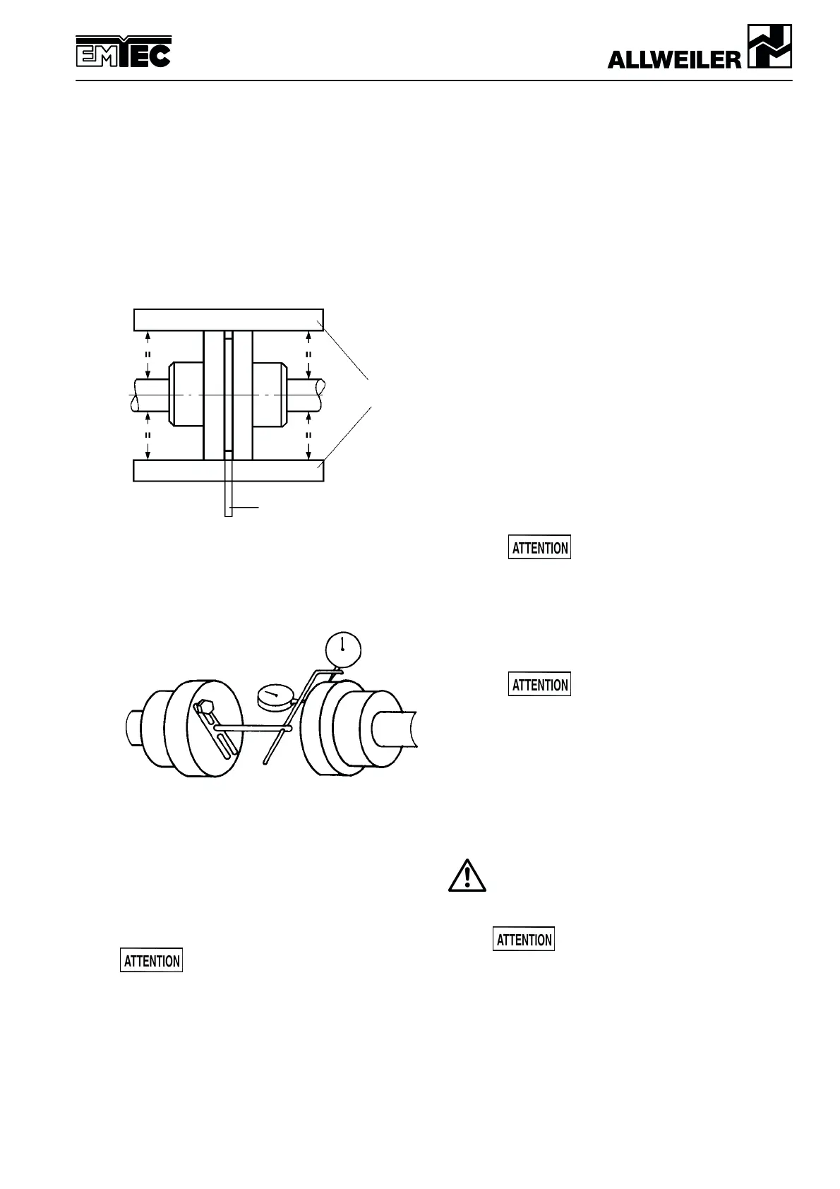
The spacing between the straight–edge laid over both
coupling halves and the respective shaft must be the
same all round the circumference.
Straight–edge
Feeler gauge
Figure 5.2: Alignment of the coupling with
straight–edge and fee–ler gauge
For couplings with a distance piece (removable coup-
lings) the alignment of the coupling can be checked
with dial gauges.
Figure 5.3: Alignment of the coupling with dial gauges
Note: The permissible axial and radial deviation,
measured on the front face of the coupling and the
coupling circumference respectively, may be max.
0.1 mm, but as far as possible should be kept below
0.05 mm.
Whe the fixing bolts have been aligned and tightened
the pump/drive motor unit must be able to be spun by
hand without pressure points.
Out–of–flush errors on the coupling may
lead to heavier wear of the coupling, the
anti–friction bearing and the shaft seal, and even cause
the shaft end to be torn off.
5.4.2 Coupling alignment in case of flanged aggregates
(if used)
In the case of pumps with flanged drive motor, the pump
and motor are precisely centered in the lantern. Align-
ment or re–alignment of the coupling is not requi–red.
Note: Improper handling, e.g. during transportation,
may impair the alignment between the pump and the
motor. In this case the pump and the motor must be re-
turned to the factory for checking.
5.4.3 Coupling alignment of special designed couplings
(if used)
Refer to the operating instructions of the coupling
manufacturer.
5.5 Assembly of pump and drive motor
If the aggregate is only assembled at the place of use,
the following worksteps take place:
1. Coat the pump and motor shaft ends with a fine film
of molybdenum disulfide (e.g. Molykote) and insert
keys.
2. Push on the coupling halves on the pump and motor
side with the aid of a pusher device.
Refer to Assembling Instruction VM 623.0004–1/...
If no puller is available, heating the coupling halves
to approx. 100°C (without rubber buffer) facilitates
pushing.
The possibility of shock and stress on
the pump and drive motor components
must be eliminated.
3. Tighten the grub screw on both coupling hubs.
4. When assembling the pump and motor, make sure
the specified gap between the coupling halves is
maintained.
The pump casing up from size 210 must
be supported additionally at the site
(see installation drawing).
5. In the case of horizontally mounted pump aggre-
gates fixed on a base plate or directly on the founda-
tion, the coupling must be aligned as described in
Section 5.4.
In the case of pump aggregates with flanged motor,
the coupling does not need to be re–aligned.
6. Mount the contact protection.
According to accident prevention regulations, the
pump must only be operated with a protection
against accidental contact.
5.6 Space required for maintenance and repair
The pump must be accessible from all
sides in order to be able to carry out
necessary visual inspections.
Adequate space must be provided for maintenance
and repair work, in particular for removal of the drive
motor or of the complete pump aggregate. It must also
be ensured that all pipelines can be attached and
removed without hindrance.