7
VM 623.0004 GB/07.00 – Ident–Nr. 550 298
5 Installation/Mounting
5.1 Installation
For installation methods and locations, please see in-
stallation drawing.
Other methods of installation are not permissible
without prior consultation with the manufacturer.
5.1.1 Place of installation
Temperature: min. –20 °C
max. +40 °C
relative air humidity:
permanent max. 85 %
temporary max. 100 %
Installation height: max. 1000 m above NN
For data differing from this, please consult the manu-
facturer.
Intensive vibrations in the vicinity of the
pump unit can lead to bearing damage and
must therefore be avoided.
5.1.2 Protective devices
In order to prevent injuries due to burns, at pumping
liquid temperatures higher than 60°C protective de-
vices in accordance with EN 809 must be provided on
site.
5.2 Foundation
5.2.1 General
The foundation may be a floor/concrete base or a load–
bearing steel foundation frame.
The foundations must be constructed in
such a way that they can take the weight of
the pump unit and all operating forces that occur.
5.2.2 Characteristics of a steel foundation frame
A steel foundation frame must be constructed in such a
way that pump feet or base plate are supported evenly
and can be secured with screw fixings.
If the base plate is only supported at four
points the pump aggregate will hang down
in the middle. This will affect the alignment of the cou-
pling and may also lead to severe noise being gener-
ated.
5.2.3 Characteristics of a floor/concrete foundation
The foundation must be horizontal, flat and clean, and
be capable of bearing the full load upon it.
Note: Concrete foundations must be executed with
standard concrete of strength class B 25 as a minimum.
5.3 Alignment of the pump aggregate
The pump aggregate must be aligned to its pre–set
height and system dimensions. This is done using sui–
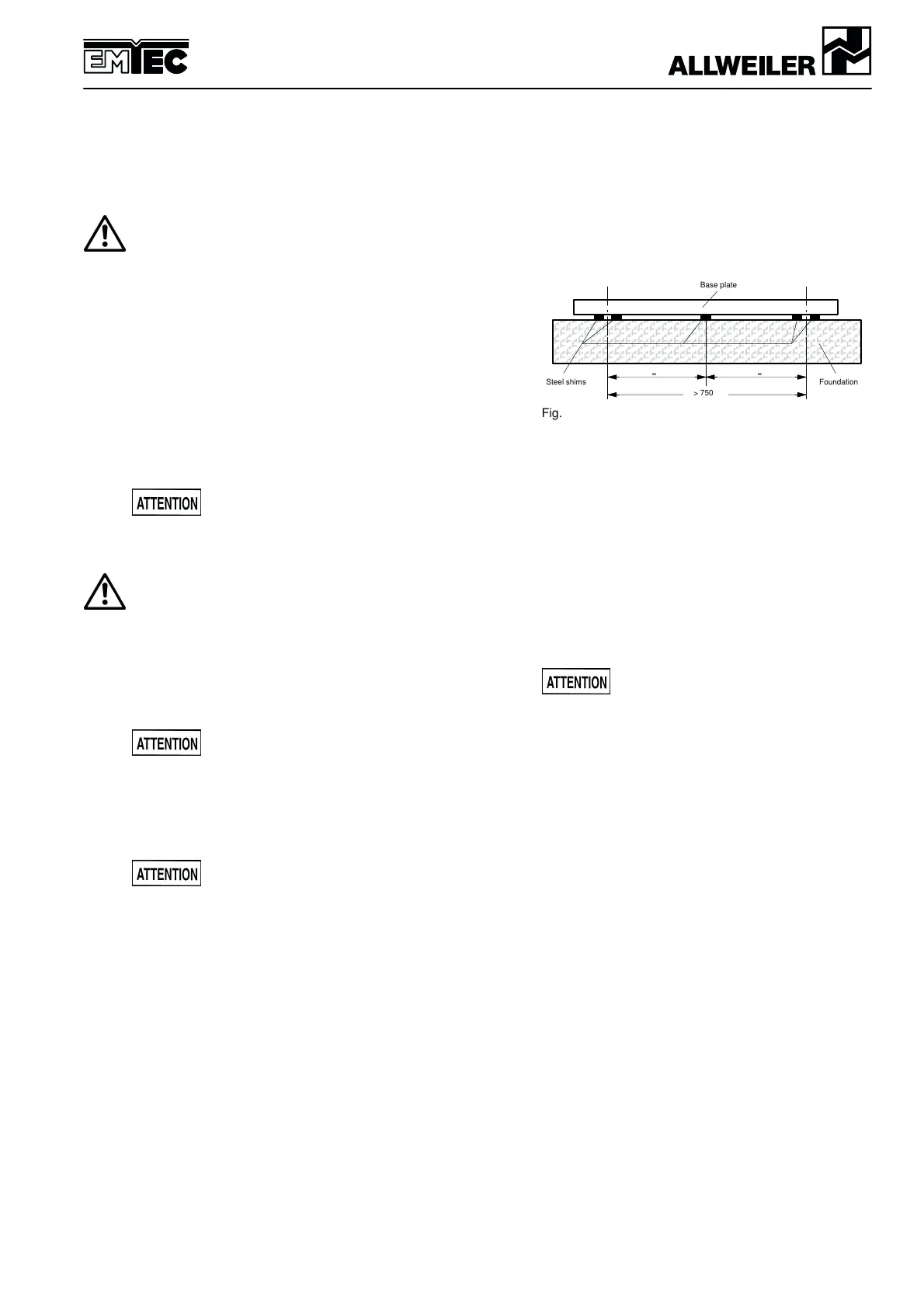
table steel shims, arranged directly adjacent to each fi–
xing bolt.
The overall height of the steel shims is determined by
the established system dimensions of the plant. The
steel shims and the base plate must be positioned
evenly and securely.
If the fixing holes are more than 750 mm apart, we re–
commend fitting additional steel shims in the middle of
the base plate.
ÄÄÄÄÄÄÄÄÄÄÄÄÄÄ
ÄÄÄÄÄÄÄÄÄÄÄÄÄÄ
ÄÄÄÄÄÄÄÄÄÄÄÄÄÄ
Steel shims Foundation
Base plate
==
> 750
Fig. 5.1: Alignment with steel shims
Horizontal alignment of the aggregate is produced by
way of flat–machined surfaces on the pump using a
machine spirit level. Measurements are taken in longi–
tudinal and transverse directions of the pump aggre–
gate.
Permissible deviation: max. 1 mm per 1 m length.
5.3.1 Fixing the pump aggregate
In order to prevent deformation of the base plate/pump,
this must first of all be screwed tightly at three points.
Before tightening the rest of the screws, spacers
should again be positioned around the screw, in order
to balance out the unevenness of the seating.
The prescribed tightening torque must be
observed.
Precise details on the shape and dimension of the fixing
are provided in the installation drawing.
5.3.2 Checking the alignment
After aligning and tightening the screws, it must be
possible to turn the pump and drive by hand, without
any strain.
Note: The pump unit should not be welded to the base
for technical installation reasons.
5.4 Checking the coupling alignment
5.4.1 Checking the coupling alignment in case of hori-
zontal setup on base plate (if used)
A complete delivered pump aggregate has been care–
fully assembled at the factory. After proper installation,
and prior to start–up of the pump aggregate, the align–
ment of the coupling must be checked.
The check can be made with a straight–edge and a
feeler gauge, or with other suitable equipment (such as
a laser alignment device).
The measurements are taken in two planes, each offset
by 90_, on the circumference of the coupling.