HP 5 OPERATOR’S MANUAL
Locate desired crop or similar crop on Table C-1 Cylinder / Concave Setting Chart. This will give
indicate a place to start. This setting may need to go up or down depending on crop and field
conditions.
To adjust concave setting, proceed as follows:
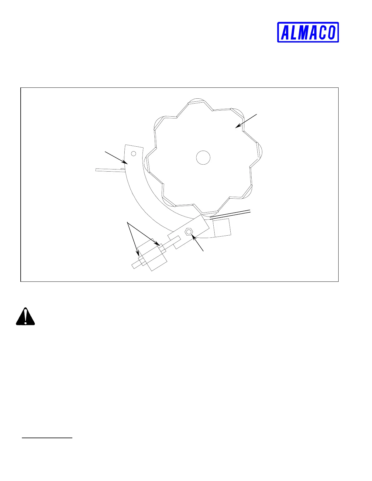
Concave
Threshing Cylinder
Lock Nuts
Concave Bolts
Cylinder / Concave
Clearance
TABLE C-4 Cylinder / Concave Clearance
DANGER!
Rotating parts can cause serious injury or death. Disengage clutch and shut engine off before
adjusting concave clearance.
1. Loosen concave bolts on both sides of the machine. Do not remove bolts unless concave is to be
removed (See FIGURE C-4 above).
2. Using the lock nuts to push or pull the concave, adjust it until the desired front concave setting is
reached. This is measured between the second concave bar and a threshing cylinder raspbar. Be
sure to move both sides evenly to keep the concave parallel to the threshing cylinder. The concave
is set on hinge bolts, adjusting the front of the concave should swing the rear of the concave into
place.
3. Secure lock nuts and side bolts when concave is in position.
4. Be sure to spin the threshing cylinder over by hand to insure there is no contact between the
cylinder and concave.
Cyclone Blower
C-10 OPERATION