59
ϑ
RFV
-X4
-R3
RFV
GND
ϑ
TB1
-R4
TB1
GND
TR
ϑ
TBW
-R5
TBW
GND
ϑ
TA.
-R6
TA
GND
ϑ
TRL
-X5
-R7
TRL
GND
ϑ
TVL
-R8
TVL
GND
ϑ
THG
-R9
THG
GND
ϑ
TWA
-R10
TWA
GND
CW.
GND
ϑ
TWE
-R12
TWE
GND
R8
R3
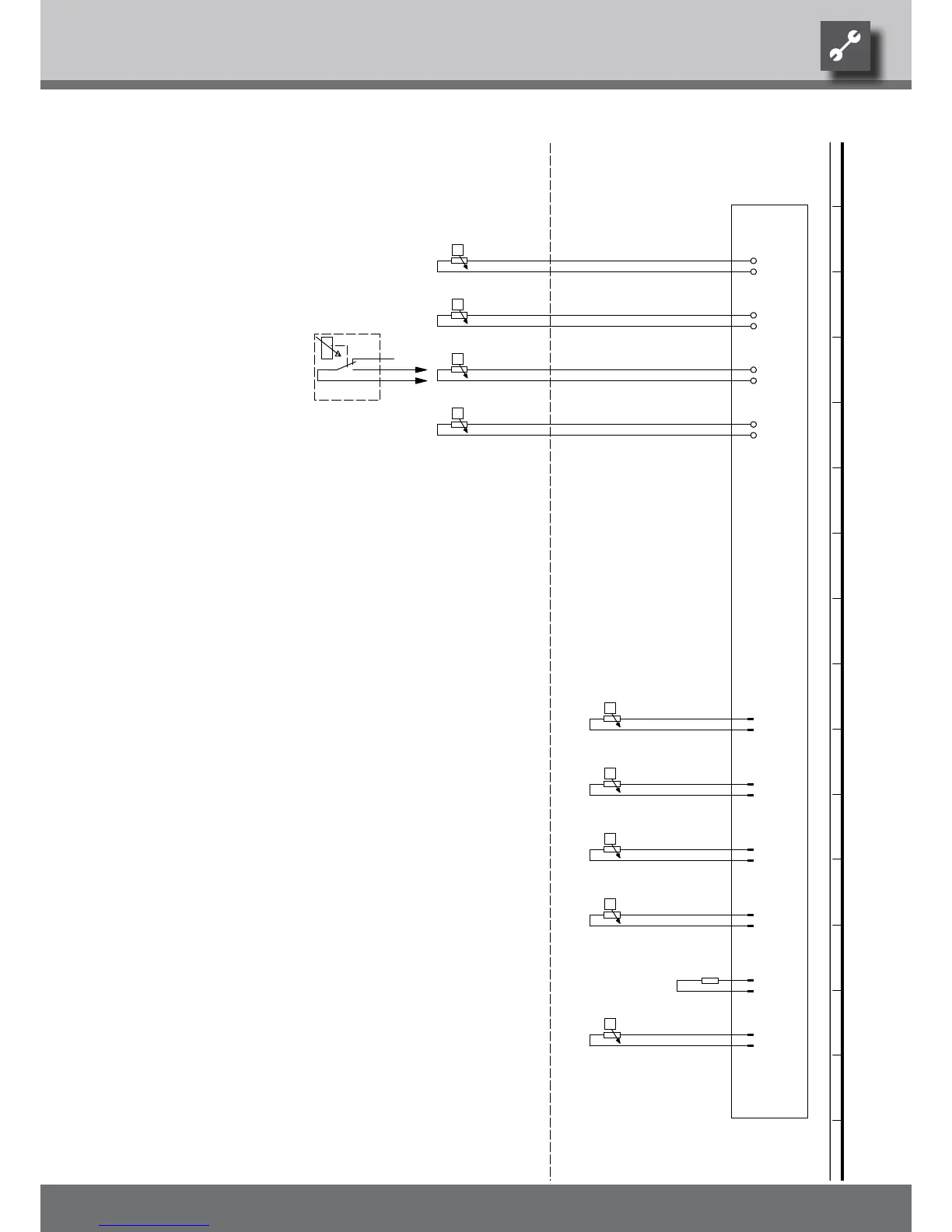
Accessories: Process water for thermostat
R7
Flow sensor
RFV
Sensor mixing circuit 1
TWA
Heat source input sensor
TVL
TWE
Operating materials
R4
R10
Y4
UK817330
R12
R9
Accessories: Remote control
Heat source output sensor
TA
Legend:
Encoding, heat pump; SWP - 162 Ohm,
Domestic hot water sensor
CW
TRL
-CW
-R11
BWT
Function
Return sensor
TB1
External sensor
Hot gas sensorTHG
R5
R11
BWT
TBW
A1
-A1
-Y4
Controller board; Attention: I-max = 6A/230VAC per contact
R6
We reserve the right to make technical changes.
UK830509/200114 © Alpha-InnoTec GmbH
Circuit Diagram 3/3 Size 2