Alpha E-Tec Plus 28NX, 33NX and 38NX - Installation
5.11 CONNECT THE MAINS SUPPLY - Figs. 5.16 and 5.17
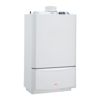
Gain access to the boiler terminal block 'D' as follows:-
Remove the case front panel, refer to Sections 7.1 and 7.2.
Remove the control panel cover 'B'.
1. Remove the one screw 'A' in Fig. 5.16.
2. Depress the two clips on the control panel cover.
3. Remove the cover 'B' from the control panel 'C'.
Two cable clamps and relevant fixing screws for optional
connection are supplied in a bag positioned in the clock
housing.
Refer to Technical Data, Section 3.6 for connection details.
The boiler is supplied with a 'Special X' type electrical
connection with a PVC <HAR> H05VV-F 3 x 0.75 cable
without a plug. If the power cable is damaged or replaced,
it must be replaced with a cable supplied by Alpha or
authorized After-Sale Technical Service. Replacement is
recommended using a qualified company in order to prevent
any risk. Ensure the cable clamp that has been fitted is
removed and connect as follows:-
Pass the mains supply cable through the cable clamp and connect
as follows:- Brown to L, Blue to N and Green/Yellow to
. Ensure
correct polarity.
Note: Ensure that the length of the earth wire is such that if the
supply cable is pulled out of its clamp the live and neutral wires
become taut before the earth wire.
Do not switch on the electrical supply at this stage.
If an external control, i.e. room thermostat or external clock is to be
fitted, remove the link between terminals 1 and 2. Pass the cable
through the cable clamp and connect it to terminals 1 and 2. (Refer
to Section 3.6).
Leave the control panel open until commissioning procedures have been completed.
Carry out electrical system checks - Short circuit, Polarity, Earth continuity and Resistance to earth with a suitable multimeter.
5.12 FITTING BOILER CONTROLS
It is recommended that Alpha controls are used with the boiler to maintain efficient and correct operation of the
boiler. Please note that using controls that are not supplied or recommended by Alpha may invalidate the boiler
warranty and may not control the boiler correctly.
Alpha offer a number of controls options from simple in-built mechanical timers to remote wireless programmable controllers.
The Alpha Climatic Programmable Modulating Boiler Energy Manager is a two-channel time and temperature programmer
with integrated thermostat and 'BUS' system to transfer data between the boiler and controller, enabling full remote control
of the boiler functions and display of information. With enhanced boiler control, the unit further increases boiler and system
efficiency. Alternatively standard programmable room thermostats or mechanical and digital boiler clocks are available.
Note: Only use a Climatic or suitable single channel Alpha controller. Do not fit a two channel controller.
Connecting Controls
Remove the control panel cover as described in Section 5.11, if it has not already been removed.
Refer to Sections 3.6 and 9.1 for electrical connections and wiring diagram.
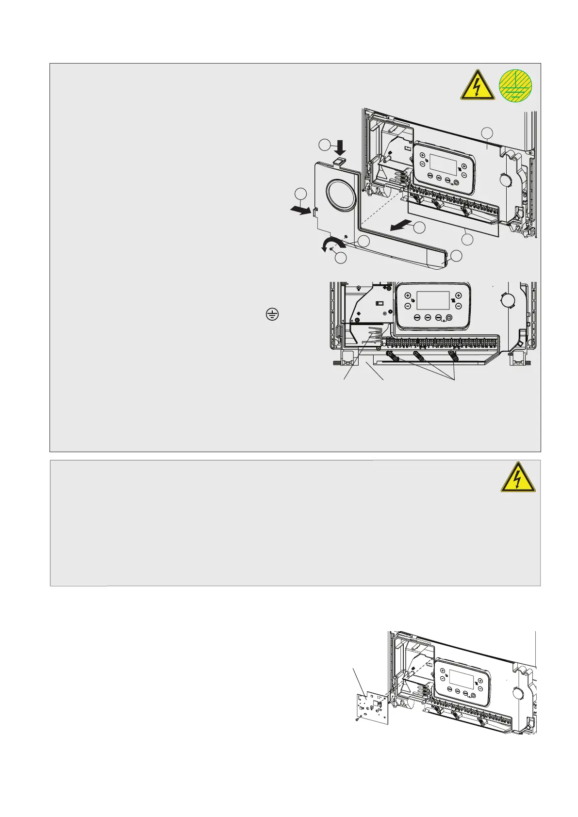
Climatic RF receiver installation
1. Plug the connecting wire onto the Climatic receiver PCB
supplied with the controller.
2. Using the two screws provided, fix the receiver PCB into
position.
3. Route the wire along the groove in the control panel to terminal
block connections 44 and 41 (the wires can be connected
either way round).
4. Remove the links between terminal blocks 1 and 2.
5. Replace the control panel cover in reverse order.
Note: Ensure all wires and connections are secured safely before replacing covers.
Fig. 5.18
Climatic receiver
Fig. 5.16
B
C
D
2
2
A
1
3
Fig. 5.17
Cable clamps
Cable entry
230 V control
29