Alpha E-Tec Plus 28NX, 33NX and 38NX - Installation
Alpha RF receiver installation
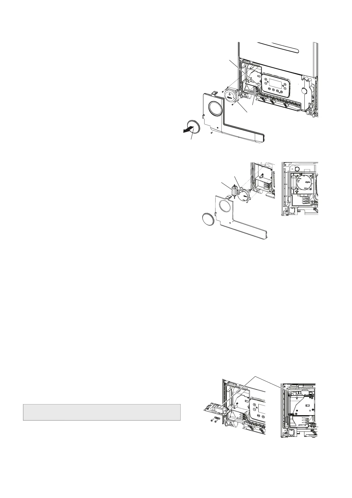
1. Remove the link between the red wires 3 and 4 and plug all
wires on to their corresponding numbers on the receiver or
clock.
2. Locate the receiver or clock onto the two pins and using the
two screws provided fix into position.
3. Route the wires through the slot in the bottom right hand
corner of the housing.
4. Remove the round blanking panel from the cover panel and
re-fit the control panel cover in reverse order.
Open Therm type installation
Note: Before purchasing / installing Open Therm type controls from an alternative manufacturer, it is the installers
responsibility to ensure they are compatible with the Alpha boiler.
Remove the control panel as described in Section 5.11, if it has not already been removed.
Refer to controls manufacturer's installation instructions for specific mounting / fitting guidance.
Route the BUS communication wires along the groove in the control panel to the terminal block connections 41 and 44 (the
wires can be connected either way round).
Ensure the link wire between terminals 1 and 2 remains in place.
Replace the control panel cover in reverse order.
Note: Refer to parameter P17 (see Section 6.14) to select the correct parameter to allow the boiler to operate with
alternative control type '1'.
Fig. 5.19
Slot for wires
Blanking panel
Alpha RF receiver
Wires
Smartech Plus receiver installation
1. Attach the shorter connecting wires from the power supply to the
Smartech Plus receiver. The black moulded plug to the connector
X1, yellow and white wires screwed into the OT connector (not
polarity sensitive).
2. Route the longer wires from the power supply along the groove in
the control panel to the boiler terminal block connections as follows:
Yellow ......to terminal 44
White ..... to terminal 41
Brown ....to terminal A
Blue ....... to terminal B
3. Using the two screws supplied, fix the Smartech receiver into
position and fit the power supply to the left.
4. Remove the links between terminal blocks 1 and 2.
5. Replace the control panel cover in reverse order.
Note: Ensure all wires and connections are secured safely before replacing the covers.
Fig. 5.20
Relay board installation
Remove the control panel cover as described in Section 5.11, if it has
not already been removed.
Mount the board by inserting it as far as it will go and fitting it into the two
special hooks
Refer to separate guide supplied with relay board before making
electrical connections to boiler main PCB or system components.
Replace the control panel and casing in reverse order.
Fig. 5.21
Power pack
Receiver
Relay board
30