6.12 CONVERTING THE BOILER TO OPERATE ON LPG
If the boiler has to be converted for LPG, obtain the relative conversion kit. The gas conversion operation
must be carried out by a competent and suitably qualified Gas Safe registered engineer.
To convert to LPG the following operations are required:
• Isolate the appliance from the electric and gas supplies.
• Replace the injector located on the upper fitting of the gas valve and re-seal the connections (Fig. 7.8).
• Re-instate gas and electric supplies.
• Calibrate the new fan speed for LPG (Section 6.14).
• Check / adjust the correct CO
2 (Section 6.13).
• Seal the gas flow rate regulation devices (if settings are modified).
• After completing the conversion, apply the sticker (supplied in the conversion kit) near the boiler data plate.
Using an indelible marker pen, delete the data relative to the old type of gas.
These adjustments must be made according to the type of gas used, given in the table (Section 3).
6.13 CO2 SET UP PROCEDURE
The air gas ratio of the boiler has been factory set and should not require adjusting during first commission.
If adjustment is recommended or required the engineer must be competent to carry out this work.
If setting the boiler on a Hydrogen mix installation (20%H2NG), for all calibration and combustion checks, refer to
the O
2
% values for the flue gas analysis. See Section 3.1.
Before starting this procedure please check the following:
The front case is fitted.
The flue system is not blocked or restricted and is to the correct specification.
The gas supply working pressure is correct and the system has been purged.
There is no recirculation in the boiler flue circuit.
The condensate trap is pre-filled.
If the flow temperatures are getting up to maximum operating temperature during the procedure it is possible to open a hot
tap to lose the heat.
Attention: the CO
2 checks must be carried out with the case fitted, while the gas valve adjustments must be carried out with
the front case removed.
Calibration of the maximum CO
2 (nominal DHW output)
Refer to Section 6.7 and enter the chimney sweep mode (open any hot tap to activate maximum mode) use the CH up and
down buttons to set the output to maximum (99%). Insert the analyser probe into the flue test point (Fig. 6.4) and check that
the CO
2 value is as specified in Section 3.1, otherwise adjust the max CO2 adjuster (Fig. 6.3). To increase the CO2 value,
turn the adjustment screw in a clockwise direction and vice versa to decrease.
Calibration of the minimum CO
2 (minimum output)
When you finish the maximum CO
2 adjustment, while maintaining the chimney sweep function active, use the CH up and
down buttons to set the output to minimum (0%). Insert the analyser probe into the flue test point (Fig. 6.4) and check that
the CO2 value is as specified in Section 3.1, otherwise adjust the minimum CO2 adjuster (Fig. 6.3). To increase the CO2
value, turn the adjustment screw (Fig. 6.3) in a clockwise direction and vice versa to decrease it.
At every gas valve adjustment, it is necessary to wait for the boiler to stabilise itself at the value set (approx. 30 sec.).
For Hydrogen fuel installations only
With Hydrogen mix installlation (20% H2NG), when setting the maximum, if the value of O
2 as specified in Section 3.1 cannot
be reached with the adjusting screw fully open, then additional adjustments are not necessary.
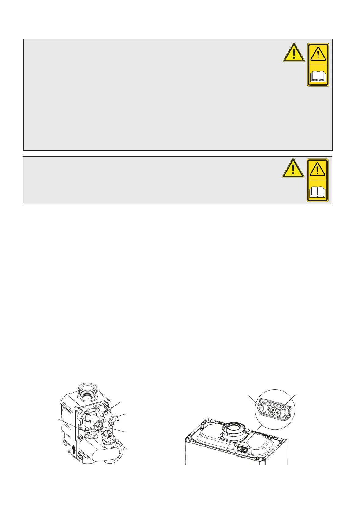
Fig. 6.3 Fig. 6.4
Outlet pressure
test point
Inlet pressure
test point
Wiring plug
+
+
Off/Set adjustment
screw (Min. CO )
2
Gas outlet flow
adjustment screw
(Max. CO )
2
Flue test point
F (+)
Air test point
A (-)
Alpha E-Tec Plus 28NX, 33NX and 38NX - Commissioning
38