Veb- MN (Excell-MCDSe 400)#A(15-5-2007)(in).doc
1
USER MANUAL FOR EXCELL 400 MCDSe
BIPOLAR
BIP
EXCELL
400 MCDS
PED
PED-BIPPED
PED-2PED-1
MAN-2MAN-1
BIPOLARMONOPOLAR
N.P.MONOPOLAR
alsa
PED-2
MAN-2
PED-1
MAN-1
BIP
MONO
HF LEAKAGE
MICRO
MACRO
MICRO AUTOBLEND
PURE
PIN POINT CONTACT
FULG FORCED
SPRAY
SOFT
BLEND-1
PURE
BLEND-2
ENDO
N.P.
PROGRAM BIPOLARMONOPOLAR
46538721
H
G
FEDCBA
I
COAG
CUT
COAGCOAG
CUT
e
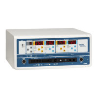
Control devices, Connection sockets, and Symbols
A
Alarm Led for the neutral plate safety circuit (red)
B Area for memories setting (storage key and selection/shifting keys )
C Area of selection and regulation of the Monopolar Cut/Coagulating Cut
D Area of selection and regulation of the Monopolar Coagulation
E Area of selection and regulation of the Bipolar Cut/Coagulating Cut
F Area of selection and regulation of the Bipolar Coagulation
G Alarm Led for the HF leakage currents control circuit
H Setting of the standard twin foot-switch pedal functioning PED
I Led for bipolar output
1 Socket PED for the twin foot-switch pedal connection (standard for the activation of the monopolar or bipolar currents)
2 Socket PED-BIP for the twin foot-switch pedal connection (non standard, and only for the activation of the bipolar currents)
3 Socket MAN-1 for the connection of the monopolar hand-switch handles
4 Socket MAN-2 for the connection of the monopolar hand-switch handles
5 Socket PED-1 for the connection of the monopolar electrodes cables with activation by foot-switch pedals
6 Socket PED-2 for the connection of the monopolar electrodes cables with activation by foot-switch pedals
7 Socket N.P for the connection of the neutral electrode cable
8 Socket BIP for the connection of the bipolar electrodes cable
b1 At disposal
b2 General mains switch (green-0/I)
b3 Socket for the mains cable with fuse block
b4 Plug for the equipotential connection
b5 Rotating regulator of the start delay of the bipolar Micro Auto coagulation (from instantaneous mode to 5sec max.)
b6 Rotating regulator of the acoustic signals intensity for the activation of the cut and coagulation
b7 Connector for interconnection to the Argon gas module
Earth protection (inside) Alternating current Attention: read the user manual
Apparatus of Class I Type CF, protected against the defibrillator effects (a CF type unit guarantees the highest safety level against direct and
indirect contacts, notably for the allowable leakage currents). The applied part type F (floating) is protected from the earth at high and low
frequencies. This kind of unit is especially indicated for direct heart application.
b1
b7