Excell MCDSe series
Rel. 1
alsa apparecchi medicali srl 12
values, as indicated in the column “I-Out”; if necessary, use the R1 pot placed on the main board (Alsa code
801463) in order to obtain the right H.F. current values on the load, as indicated in the column “Current”:
Setting Current (A) I-Out (Hex)
31
0.22
24
47
0.32
34
71
0.50
54
9d
0.70
75
CALIBRATION OF THE NEUTRAL PLATE CIRCUIT
Connect the probe of the oscilloscope to the point indicated with TP2 on the board for the hand-switch
control (Alsa code: 801462).
Connect a 250ohms resistor to the terminals of the neutral plate.
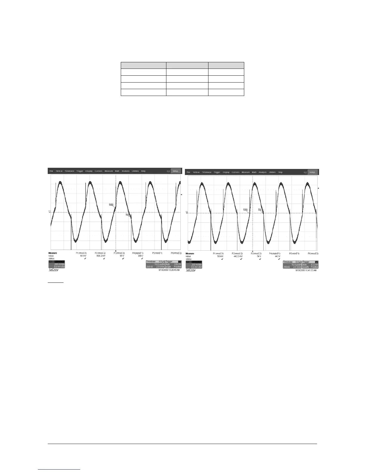
Calibrate the R27 pot in order to obtain a sinusoidal waveform, which is symmetric with respect to the
horizontal axis. The following Figures show an example of right and wrong waveform:
Wrong Right
NOTE: The points indicated with “start” and “end” must coincide as much as possible with the X axis.
At the end of the calibration, the frequency of the sinusoidal wave is about 100kHz; anyway, it must be said
that the calibration establishes the exact “coupling point” of the neutral plate circuit, while the frequency
represents its natural consequence.
The control circuit of the contact between the plate and the patient verifies the condition for an optimum
contact as well as some intermediate levels, which are shown to the operator through the lights, placed into
the section indicated on the panel with “N.P.”. Notably, we can distinguish the following cases:
1) from 0 to 160 ohms: optimum contact. All the luminous signals that concern the neutral plate are
switched off. The equipment can be used by setting any power, and the supply will correspond to
what has been set;
2) from 160 to 190 ohms: the quality of the contact begin to decrease. The first luminous signal lights
up in order to inform the operator on the current status of the contact;
3) from 190 to 250 ohms: the quality of the contact worsens considerably. Also the second luminous
signal lights up in order to capture the attention of the operator. Besides this threshold, the