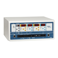
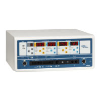
Excell MCDSe series
Rel. 1
alsa apparecchi medicali srl 2
INDEX
INSTRUMENTS REQUIRED ............................................................................................................................ 2
INTRODUCTION ............................................................................................................................................... 2
PRELIMINARY .................................................................................................................................................. 4
CALIBRATION OF THE POWER SUPPLY SECTION – SETTING OF THE LOW VOLTAGES ..................... 5
CALIBRATION OF THE MASTER MICROCONTROLLER BOARD REFERENCE VOLTAGE ...................... 5
CALIBRATION OF THE SLAVE MICROCONTROLLER BOARD REFERENCE VOLTAGE .......................... 6
CALIBRATION OF THE POWER SUPPLY SECTION –SETTING OF THE HIGH VOLTAGE ........................ 6
CONTROL AND CALIBRATION OF THE INTERNAL PARAMETERS ............................................................ 6
CALIBRATION OF THE READING BOARD “VOLTAGE/OUTPUT CURRENT” .............................................. 7
MATCHING OF THE POWER MOSFETS DRAIN CURRENT ........................................................................ 9
CALIBRATION
OF THE OUTPUT VOLTAGE PEAK FOR EACH MODE .........................................................9
CALIBRATION
OF THE MAXIMUM POWER STAGE MOSFETS CURRENT FOR EACH FUNCTION .........10
CONTROL OF THE H.F. LEAKAGE CURRENTS .......................................................................................... 11
CALIBRATION OF THE OUTPUT CURRENT ................................................................................................ 11
CALIBRATION OF THE NEUTRAL PLATE CIRCUIT .................................................................................... 12
SECTION FOR THE ARGON GAS COAGULATOR ...................................................................................... 13
LIST OF THE ERROR CODES ....................................................................................................................... 14
SCHEMATIC DIAGRAMS, COMPONENTS DISPOSITION AND OTHER LISTS ......................................... 17
INSTRUMENTS REQUIRED
• True RMS Digital multimeter example: TEKTRONIX DMM912
• Oscilloscope with Bandwidth > 60 MHz example: TEKTRONIX TDS3012
• Current probe with Bandwidth 200 Hz÷50 MHz example: TEKTRONIX P6021
• Analyser for electrosurgery example: FLUKE DNY 454A
• Flowmeter full scale 20lt/min
• Manometer full scale 3bar
INTRODUCTION
The electrosurgical units EXCELL of the series MCDSe are composed of the following sections:
• Power supply section;
• R.F. power stage;
• Power reading section;
• Microcontroller section;
• Section for activations by hand-switch and neutral plate contact control;
• Argon gas section control (/A models only).
The power supply section allows the following voltages:
o +5V for the functioning of the master and slave microcontroller sections; this voltage is delivered by
an integrated switching regulator LM2676 properly calibrated;
o +15V and -15V for the control and driving circuits; +15V are obtained by a regulator LM2676 that
has been calibrated expressly to supply this voltage; -15V are delivered by a voltage regulator
LM7915 LDO , needed for all the circuits that require a dual supply;
o +24V for the functioning of the Argon gas solenoid valves, obtained by a voltage regulator LM7824
LDO;