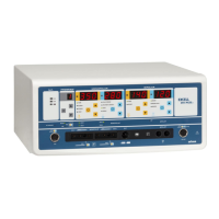
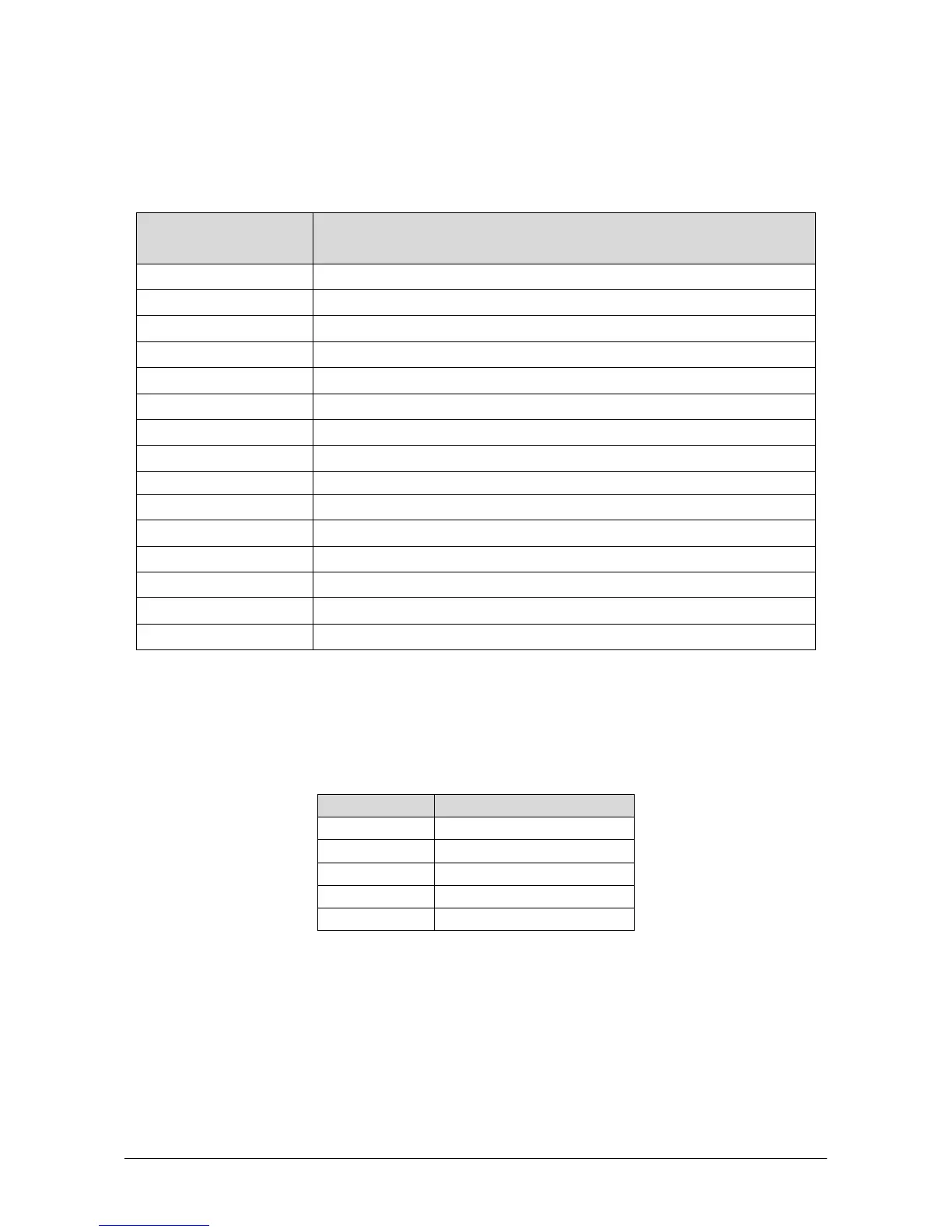
Excell MCDSe series
Rel. 1
alsa apparecchi medicali srl 5
from the visualization of the calibration parameter to the visualization of the power setting (by remaining in
the calibration mode); in order to proceed to the next calibration, it is necessary to press the CAL button
again and go back to the mode of the monopolar section with the blinking displays. The following Table
shows the whole list of the selectable tests:
Monopolar Cut Display
Test n°
Description
00
Continuous supply of the power stage
01
Internal parameters of the R.F. section
02
Functioning of the R.F. section without feed-back
03
Peak voltage R.F. (Voutpk)
04
Drain current into the mosfets of the R.F. section
05
R.F. leakage current with control made by the software
06
R.F. leakage current without control
07
Start/Stop impedance adjustment for the automatic bipolar mode
08
Not Used
09
Reading of the data that come from the analogical inputs of the micro Slave
0b
Visualization of the current software release
0C
Loading of the default values
0d
Reading of the errors memorization
0E
Cancellation of the errors list into the E
PROM
CALIBRATION OF THE POWER SUPPLY SECTION – SETTING OF THE LOW VOLTAGES
Before proceeding with the calibration of the section that controls the supply of the power R.F. generator
stage, it is necessary to verify the continuous low voltages. To do that, connect the positive terminal of a
multimeter to the points indicated in the following Table:
Test Point Voltage (VDC)
L6 +5.08
L7 -15V
L8 +15V
U6 (pin 3) +24V
U13 (pin 3) +5V
Set the R31 pot placed on the Power Supply board (Alsa code: 801471) in order to set exactly the +5V
continuous voltage for the microcontroller section.
CALIBRATION OF THE MASTER MICROCONTROLLER BOARD REFERENCE VOLTAGE
If present, remove the J11 jumper.
Connect a multimeter between the test point J10 and GND; set the R102 pot placed on the Master
Microcontroller board (Alsa code: 801469) in order to obtain a voltage of 5.00V (± 0.01V).
Once the calibration has been performed, close the J11 jumper.