Excell MCDSe series
Rel. 1
alsa apparecchi medicali srl 6
CALIBRATION OF THE SLAVE MICROCONTROLLER BOARD REFERENCE VOLTAGE
If present, remove the J12 jumper.
Connect one multimeter between the pin n°2 of J12 and GND; set the R60 pot placed on the Slave
Microcontroller board (Alsa code: 801467) in order to obtain a voltage of 5.00V (± 0.01V).
Once the calibration has been performed, close the J12 jumper.
CALIBRATION OF THE POWER SUPPLY SECTION – SETTING OF THE HIGH VOLTAGE
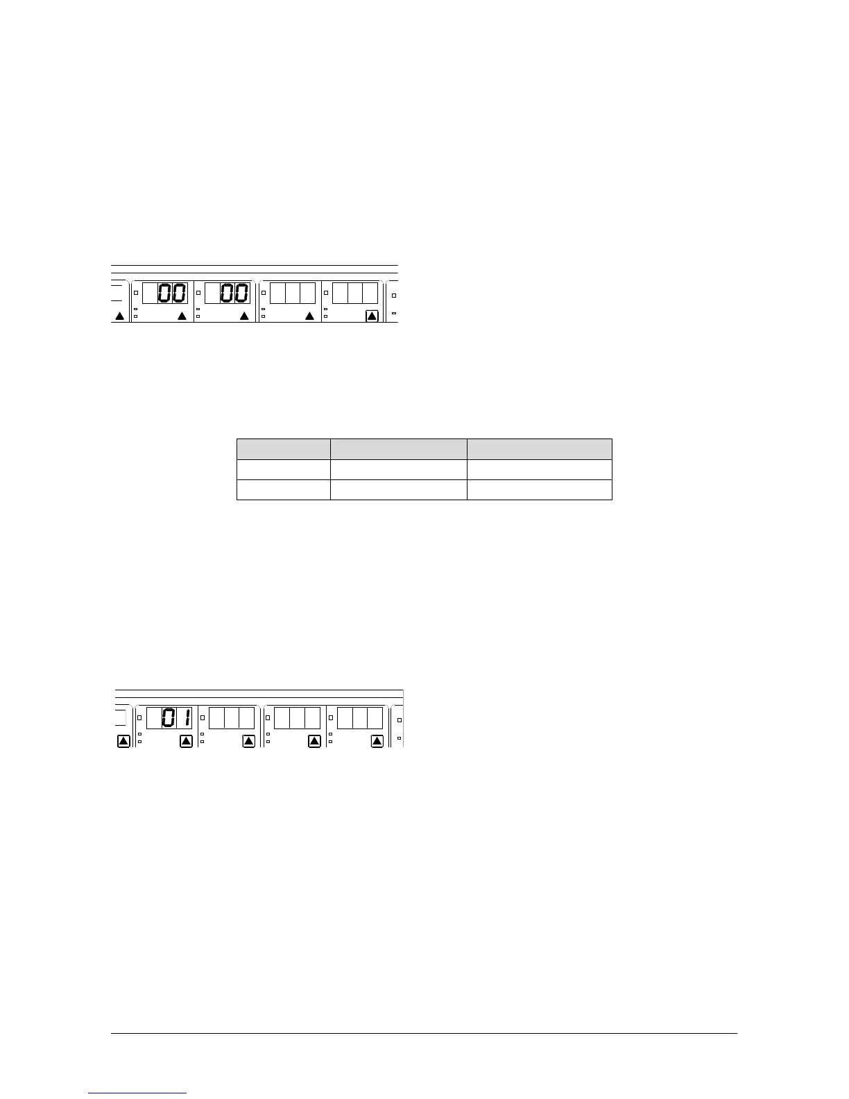
Press the CAL button; when the displays blink, set the monopolar Cut section, as shown into the Figure:
MONOPOLAR BIPOLAR
RAM
PURE
BLEND-1
FULG FORCED
PIN POINT CONTACT
PURE
BLEND
MICRO CV
MICRO HC
Press the CAL button so that the displays stop blinking. Connect one load of 500ohm/100W to J1 and J2
connectors placed on the Supply board (Alsa code: 801471); connect one multimeter in order to measure
the voltage in parallel to the load. Set the R52 (maximum level) and the R24 (minimum level) pots to obtain
the values shown in the following Table:
Setting Voltage (VDC) Monopolar Coag
05
E6 135,5
0C 8,8
With the blinking displays, and by setting 05 into the monopolar Coagulation section, it is
possible to read the converter A/D “AD5” that sends the value, detected by the
microcontroller, about the supply voltage of the power section.
As these calibrations are interactive, it is advisable to repeat the control of the minimum and maximum
levels at least twice.
CONTROL AND CALIBRATION OF THE INTERNAL PARAMETERS
Press the CAL button; when the displays blink, set the monopolar Cut section, as shown into the Figure:
MONOPOLAR BIPOLAR
RAM
PURE
BLEND-1
FULG FORCED
PIN POINT CONTACT
PURE
BLEND
MICRO CV
MICRO HC
Connect the current probe to one of the conductors of the damping resistor, placed at the bottom of the
metal box.
Press the CAL button so that the displays stop blinking; set 42 in the monopolar Pure Cut mode. Switch the
equipment on: the measured current must be 331mA (± 3%). If the measured value is deeply different with
respect to the one indicated, operate on the loops of the L1 inductor, by changing its position around the
core until the indicated value is obtained (ATTENTION: In order to modify the position of the loops, it is
necessary to take the R.F. generator board away, then make the intervention, and finally place the generator
board again. At this point, repeat the measure).
Set 12 in the bipolar Pure Cut mode; by switching the equipment on, the measured current must be 70mA (±
2mA).